
Troubleshooting guide


MOBILE ANORAD GANTRY SYSTEM
- 29 -
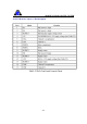
2.8 24V Power Supply
Pin #
Signal
Colour
Connected to
1 LIVE Red
Pin 2 of the X and Y-axis Driver Main Power Connector
2 NEUTRAL Black
Pin 3 of the X and Y-axis Driver Main Power Connector
3 EARTH Green
Pin 4 of the X and Y-axis Driver Main Power Connector
4 GROUND Blue
Pin 5 of the X-axis Committed I/O connector
Pin 7 of the Y-axis Committed I/O connector
Pin 2 of the Relay Circuit Green connector
5 24V Yellow
Pin 1 of the Relay Circuit Green connector
Pin 1 of the Relay circuit Top connector
Pin 2 of the Emergency Stop switch
Table 20: 24V Power Supply ( for enabling X and Y axis )