MOBILE ANORAD GANTRY SYSTEM -1-
MOBILE ANORAD GANTRY SYSTEM Mobile Anorad Gantry System -2-
MOBILE ANORAD GANTRY SYSTEM TABLE OF CONTENTS 1 INTRODUCTION 2 SAX-5/230 DIGITAL SERVO AMPLIFIER (X & Y AXIS) 3 PIC 15/200 BRUSHLESS MOTOR SERVO AMPLIFIER (Z AXIS) 4 DSPACE DS1103 PPC CONTROLLER BOARD 5 OPERATOR CONTROL PANEL LADDER DIAGRAMS 6 TROUBLESHOOTING GUIDE APPENDIX 1: MEASURED VOLTAGES OF J5 CONNECTOR APPENDIX 2: DIMENSIONAL DRAWINGS APPENDIX 3: PCB SCHEMATIC DIAGRAMS APPENDIX 4: PCB PHOTO-PLOTS APPENDIX 5: WIRING DIAGRAMS APPENDIX 6: SIMULINK/CONTROLDESK PROGRAMS APPENDIX 7: DATASHEET
MOBILE ANORAD GANTRY SYSTEM List of Figures: Figure 1: Dedicated I/O Figure 2: Panel Layout Figure 3: Motor Power Connection Figure 4: Power Terminal Connections Figure 5: SAX-5/230 Servo Amplifier Relay Circuit Figure 6: Encoder / Hall sensor Pin Assignment Figure 7: Analog input with single-ended source Figure 8: RS232 Interface Figure 9: PIC 15/200 Connectors Location Figure 10: Block Diagram of the PIC 15/200 Figure 11: Detail Block Diagram of the PIC 15/200 Figure 12: Wiring connections of the PIC 15/2
MOBILE ANORAD GANTRY SYSTEM List of Tables: Table 1: Dedicated features Table 2: Connector Types Table 3: Main Power Connection Pinout Table 4: Auxiliary Power Connection Pinout Table 5: 9 Pin D_Type Male Connector Pinout Table 6: X Axis 9 Pin D_Type Male Connector Pinout Table 7: Y Axis 9 Pin D_Type Male Connector Pinout Table 8: 15 Pin D_Type Female Connector Pinout Table 9: X Axis 15 Pin D_Type Female Connector Pinout Table 10: Y Axis 15 Pin D_Type Female Connector Pinout Table 11: 9 Pin D_Type Female Co
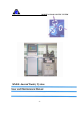
MOBILE ANORAD GANTRY SYSTEM 1 Introduction The User and Maintenance Manual is written for the design engineer or technician who will connect and operate the Mobile Anorad Gantry System.
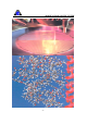
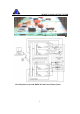
MOBILE ANORAD GANTRY SYSTEM Overall System Layout of the HPMC PC and Anorad Gantry System -7-
MOBILE ANORAD GANTRY SYSTEM Draft Layout Sketch of the HPMC PC and Anorad Gantry System • Go to: http://www.anorad.com/onlineCatalog/gantryxy.htm for the Anorad Gantry System’s Specifications and Outline drawings. • Go to: http://www.anorad.com/technicalSupport/5UAxisChassis.pdf for the 5U Axis Chassis PC Serv Configuration Hardware Maintenance Manual. • Go to: http://www.anorad.com/technicalSupport/highVoltageBrushless.pdf for the Zaxis High Voltage Brushless D.C.
MOBILE ANORAD GANTRY SYSTEM 1.1 Warning Messages Various warning messages are placed on various strategic locations of the HPMC PC workstation and the Mobile Anorad Gantry System to warn and guide the engineer as well as the operator to safely operate the entire machine setup.
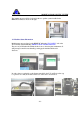
MOBILE ANORAD GANTRY SYSTEM The warning messages will also be heard via the two speaker systems installed in the HPMC PC cabinets as shown on the right. 1.2 Machine Status Information Machine status tags are placed on the HPMC PC indicating “UP / DOWN” and on the Anorad Gantry System indicating “PRODUCTION / MAINTAINANCE”. They are very useful when the machine breaks down or when it requires maintenance. It will prevent personnel from accidentally powering up the machine which can be disastrous.
MOBILE ANORAD GANTRY SYSTEM 1.2 Security In addition to the password protected screen saver, both the front and back doors of the HPMC PC workstation can be locked to prevent any unauthorized access to the machine setup. In case the keys are lost, a set of spare keys are enclosed in the emergency glass container. Break the glass to retrieve the spare keys inside during emergency.
MOBILE ANORAD GANTRY SYSTEM 2 SAX-5/230 Digital Servo Amplifier (X & Y Axis) The Saxophone series of servo amplifiers for Permanent Magnet Synchronous Motors (PMSM) incorporates digital velocity loop, digital current loop and sinusoidal commutation. Permanent Magnet Synchronous Motors, or Brushless AC (DC) motors (BLM) are used in high performance drives for machine tools and robotics.
MOBILE ANORAD GANTRY SYSTEM 2.1 General Structure and Connection Figure 1: Dedicated I/O For three phases supply voltage: • The circuit breaker current rating should be between 150% to 200%, of the amplifier’s current. • The circuit breaker voltage rating should be 460 VAC. • The contactor should be up to 150% of the amplifier’s current. For one phase supply voltage: • The circuit breaker current rating should be between 200% to 300%, of the amplifier’s current.
MOBILE ANORAD GANTRY SYSTEM 2.
MOBILE ANORAD GANTRY SYSTEM 2.3 Connections The Figures below show the front panel of the Saxophone.
MOBILE ANORAD GANTRY SYSTEM 2.4 Connector Types Table summarizes the different types of connectors used by the Saxophone.
MOBILE ANORAD GANTRY SYSTEM 2.5 Wiring and Mounting 2.5.1 Wiring Proper wiring, grounding and shielding techniques are important in obtaining good servo operation and performance. Incorrect wiring, grounding or shielding can cause erratic servo performance or even complete failure. 1) Keep motor wires as far as possible from the signal level wiring (feedback signals, control signals, etc.).
MOBILE ANORAD GANTRY SYSTEM 2.6 Connectors The following sections provide the pin outs for the Saxophone connectors. Schematics for certain cables are also provided. 2.6.
MOBILE ANORAD GANTRY SYSTEM - 19 -
MOBILE ANORAD GANTRY SYSTEM 2.6.2 Auxiliary Power Connector Pin # 1 2 Signal APS1 (24V) APS2 (24V) Colour Red Black Connected to Pin 5 of the 24V Power Supply Pin 4 of the 24V Power Supply Table 4: Auxiliary Power Connection Pinout 2.6.
MOBILE ANORAD GANTRY SYSTEM Figure 5: SAX-5/230 Servo Amplifier Relay Circuit 2.6.4 Pin # 1 2 4 5 6 X Axis Committed I/O Connector Signal FLS RLS ENABLE ENRET STOP Colour Connected to Purple Grey White Black Blue Pin 2 of the Relay circuit Top connector Pin 3 of the Relay circuit Top connector Pin 4 of the Relay circuit Top connector Pin 4 of the 24V Power Supply Pin 1 of the Emergency Stop switch Table 6: X Axis 9 Pin D_Type Male Connector Pinout 2.6.
MOBILE ANORAD GANTRY SYSTEM 2.6.
MOBILE ANORAD GANTRY SYSTEM 2.6.
MOBILE ANORAD GANTRY SYSTEM 2.6.8 Y Axis Feedback A Connector Pin # 3 5 6 14 15 Signal SUPRET CHACHA CHBCHB Colour Grey Grey Grey Grey Grey Connected to Pin 28 of the J5 connector Pin 24 of the J5 connector Pin 23 of the J5 connector Pin 26 of the J5 connector Pin 25 of the J5 connector Table 10: Y Axis 15 Pin D_Type Female Connector Pinout 2.6.
MOBILE ANORAD GANTRY SYSTEM 2.6.10 X Axis Analog I/O Connector Pin # 1 3 Signal ANLIN1+ ANLRET Colour Grey Grey Connected to Pin 5 of the J5 connector Pin 6 of the J5 connector Table 12: X Axis 9 Pin D_Type Female Connector Pinout 2.6.
MOBILE ANORAD GANTRY SYSTEM 2.6.12 Comm.
MOBILE ANORAD GANTRY SYSTEM 2.7 Power Up Before applying power, make sure that the AC supply is within the unit's specifications i.e. nominal operating AC voltage of 230VAC and rated phase continuous RMS current of 5A. 2.7.1 Voltage supply The Saxophone SAX-5/230 is designed to operate from a 1-phase voltage source. It can be connected directly to the line voltage. It is not necessary to use an isolation transformer.
MOBILE ANORAD GANTRY SYSTEM - 28 -
MOBILE ANORAD GANTRY SYSTEM 2.
MOBILE ANORAD GANTRY SYSTEM 2.
MOBILE ANORAD GANTRY SYSTEM 2.10 Emergency Stop Switch Pin # 1 2 Connected to Pin 6 of the X-axis Committed I/O connector Pin 6 of the Y-axis Committed I/O connector Pin 5 of the 24V Power Supply Table 22: Emergency Stop switch 2.11 Saxophone Setup and Initialization After completing all the connections, it is necessary to setup and initialize the system.
MOBILE ANORAD GANTRY SYSTEM 3 PIC 15/200 Brushless Motor Servo Amplifier (Z Axis) The PICCOLO series of miniature servo amplifiers for brushless DC Motors is designed for motion systems where the motor's trapezoidal commutation is performed by the amplifier. The servo amplifier incorporates custom mixed analog/digital ICs and hybridized power stage. The basic configuration is a current mode amplifier. No trimmers are used in the basic version. It meets UL508c and the suitable CE regulations.
MOBILE ANORAD GANTRY SYSTEM 3.
MOBILE ANORAD GANTRY SYSTEM 3.
MOBILE ANORAD GANTRY SYSTEM 3.
MOBILE ANORAD GANTRY SYSTEM Z Axis Driver Pin # Signal 3 6 7 8 9 ------ CMRET CREF+ CREF+VCC VCCRET +5V Ha HARET Hb Hc Connected to Pin 36 of the J5 connector Pin 35 of the J5 connector Pin 36 of the J5 connector Pin 29 of the J5 connector Pin 27 of the J5 connector Pin 1 of the Z axis COM 3 connector Pin 7 of the Z axis COM 3 connector Pin 6 of the Z axis COM 3 connector Pin 2 of the Z axis COM 3 connector Pin 3 of the Z axis COM 3 connector Table 24: Wiring conne ctions of the PIC 15/200 Figure 14:
MOBILE ANORAD GANTRY SYSTEM Figure 15: Actual wiring of the Z-axis Motor 3.
MOBILE ANORAD GANTRY SYSTEM 3.7 PIC STARTER The PIC STARTER is an add on interconnection board for the PIC servo amplifier that plugs on top of the amplifier. The purpose of this board is the translation of the PIC solder type pins into screw type terminals thus enabling easy connectivity for evaluation and low quantity applications. One to one relationship between board terminals and the pins of the PIC is kept.
MOBILE ANORAD GANTRY SYSTEM Table 26: DIP Switches settings of the PIC Starter Figure 16: Circuit Diagram of the AOK, SO1, SO2 and SO3 LEDs Table 27: LED Indications of the PIC Starter for troubleshooting - 39 -
MOBILE ANORAD GANTRY SYSTEM 4 DSPACE DS1103 PPC Controller Board The DS1103 PPC controller board is inserted directly in the PC.
MOBILE ANORAD GANTRY SYSTEM Figure 17: The dSPACE DS1103 PPC controller board Figure 18: The ROBO-678 single board computer Figure 19: DS1103 and ROBO-678 in the DAQCON Industrial Pentium III Computer - 41 -
MOBILE ANORAD GANTRY SYSTEM 4.1 Installing the DS1103 in the PC The DS1103 PPC Controller Board contains a Plug and Play circuit that can be used with ISA motherboards containing a Plug and Play BIOS. By default, the address switches on the DS1103 board are set to 000(0x0000), which enables the Plug and Play feature. Figure 20: The DS1103 Address Switches To install the DS1103 board in the host PC 1) Turn off the host PC and disconnect it from the mains. 2) Open the enclosure of the PC.
MOBILE ANORAD GANTRY SYSTEM 5) Close the enclosure, reconnect the PC to the mains and turn it on. The host PC should boot as usual. 6) If it does not, switch off the power supply immediately and check the insertion of the board. 4.2 Configuring the System The dSPACE real-time hardware is managed by the Hardware Manager integrated in ControlDesk. The Hardware Manager is used to check and modify the configuration of the dSPACE system.
MOBILE ANORAD GANTRY SYSTEM If the Plug and Play feature has been used when installing the DS1103 PPC Controller Board, the board has been configured automatically. No further configuration is necessary. When starting the Hardware Navigator of ControlDesk, the DS1103 is displayed in the Navigator in the top left of the main window. The system is ready to run real-time applications on the board. To view the board properties 1) In the Navigator, double-click the appropriate DS1103 board.
MOBILE ANORAD GANTRY SYSTEM Using the adapter cables coming with the board, these connectors can be linked to six 50pin female SUB-D connectors (labeled P1A, P1B, P2A,...). The following figure shows the numbering used (viewed from the top of the female connectors).
MOBILE ANORAD GANTRY SYSTEM 4.3.1 Analog Connector (P1) The following table shows the specifications of the signals sorted by the pin numbers of the 100-pin connector.
MOBILE ANORAD GANTRY SYSTEM - 47 -
MOBILE ANORAD GANTRY SYSTEM Table 28: Analog Connector (P1) - 48 -
MOBILE ANORAD GANTRY SYSTEM 4.3.2 Digital Connector (P2) The following table shows the specifications of the signals sorted by the pin numbers of the 100-pin connector.
MOBILE ANORAD GANTRY SYSTEM - 50 -
MOBILE ANORAD GANTRY SYSTEM Table 29: Digital Connector (P2) - 51 -
MOBILE ANORAD GANTRY SYSTEM 4.3.3 Incremental Encoder/Digital Connector (P3) The following table shows the specifications of the signals sorted by the pin numbers of the 100-pin connector.
MOBILE ANORAD GANTRY SYSTEM - 53 -
MOBILE ANORAD GANTRY SYSTEM Table 30: Incremental Encoder/Digital Connector (P3) - 54 -
MOBILE ANORAD GANTRY SYSTEM 5 Operator Control Panel Ladder Diagrams - 55 -
MOBILE ANORAD GANTRY SYSTEM - 56 -
MOBILE ANORAD GANTRY SYSTEM - 57 -
MOBILE ANORAD GANTRY SYSTEM - 58 -
MOBILE ANORAD GANTRY SYSTEM - 59 -
MOBILE ANORAD GANTRY SYSTEM 6 Troubleshooting Guide - 60 -
MOBILE ANORAD GANTRY SYSTEM Appendix 1: Measured Voltages of J5 Connector DS1103 Conn Pin No SUB-D Conn Pin No Descriptions J5 Conn Pin No Descriptions Measured Values NC NC NC 1 +5VFU NC GND GND GND 2 Common 0V P2-6 NC P1-48 GND P2-29 P2-30 P3-41 P3-42 P3-37 P3-38 P3-39 P3-40 P2-5 NC P1-47 GND P2-31 P2-32 P3-49 P3-50 P3-45 P2A-18 NC P1A-25 GND P2B-22 P2A-22 P3B-24 P3A-24 P3B-7 P3A-7 P3B-40 P3A-40 P2B-18 NC P1B-25 GND P2B-6 P2A-6 P3B-9 P3A-9 P3B-41 Digital I/O (out) NC 14-bit DAC GND D
MOBILE ANORAD GANTRY SYSTEM P3-46 P3-47 P3-48 GND P3A-41 P3B-25 P3A-25 GND Digital IE 0 ° Digital IE 90°° Digital IE 90°° GND 24 25 26 27 Y_CH1AY_CH1B+ Y_CH1BRTNF -0.021V 3.847V -0.021V 0V GND GND GND 28 RTNF 0V 5V 5V 5V 29 5VF 4.9V 5V 5V 5V 30 5VF 4.9V NC NC NC 31 +12VF NC NC NC NC 32 -12VF NC P2-7 P2B-2 Digital I/O (out) 33 Z_EN 4.
MOBILE ANORAD GANTRY SYSTEM Appendix 2: Dimensional Drawings Elmo SAX 5/230 digital driver - 63 -
MOBILE ANORAD GANTRY SYSTEM - 64 -
MOBILE ANORAD GANTRY SYSTEM - 65 -
MOBILE ANORAD GANTRY SYSTEM - 66 -
MOBILE ANORAD GANTRY SYSTEM Appendix 3: PCB Schematic Diagrams - 67 -
MOBILE ANORAD GANTRY SYSTEM - 68 -
MOBILE ANORAD GANTRY SYSTEM - 69 -
MOBILE ANORAD GANTRY SYSTEM Appendix 4: PCB Photo-plots - 70 -
MOBILE ANORAD GANTRY SYSTEM - 71 -
MOBILE ANORAD GANTRY SYSTEM Appendix 5: Wiring Diagrams Wiring Diagram of the X, Y and Z axis of the Anorad Gantry System - 72 -
MOBILE ANORAD GANTRY SYSTEM Appendix 6: Simulink/ControlDesk Programs - 73 -
MOBILE ANORAD GANTRY SYSTEM - 74 -
MOBILE ANORAD GANTRY SYSTEM Appendix 7: Datasheets For detail Datasheet of Elmo SAX 5/230 digital driver, refer to the website: www.elmomc.com/support/datasheets-files/LEF_SAX_EN_0500.pdf For detail Datasheet of Elmo PIC 15/200 brushless motor driver, refer to the website: www.elmomc.com/support/datasheets-files/LEF_PIC_EN_0500.pdf For detail Datasheet of dSPACE DS1103 controller board, refer to the website: http://www.dspace.de/Download/PDFFiles/Products/07_1103.
MOBILE ANORAD GANTRY SYSTEM - 76 -