
Specifications


Modular I/O Configuration Guide68
Installation Considerations
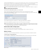
Switch 1 helps configure the MM935’s master mode and CAN ID. To set a switch ON, move it to the up position.
To set the MM935 to clock master mode, set SW1-1 to ON. Otherwise, set it to OFF.
To initialize all module parameters to factory default values, press the INIT button during power-on.
Setting the CAN ID
Each frame must be fitted with an FC972 Remote to externally configure all modules (except analog line in/out and WC984) and
control mic preamps remotely using a web browser. Install only one FC972 per frame and up to two SY983s (for redundant op-
eration, differentiated by Master/Slave setting).
A Module's system ID consists of the Frame ID + module CAN ID. The Frame ID is determined by the FC972’s IP Address/Sub-
net/Host Address. The FC972 must be assigned a unique IP Address based on the frame’s role within the system. A CAN ID must
be set for each externally controllable module. Most modules have 32 CAN ID settings available but the AD914 Remote Mic Pre-
amp has 16.
The FC972 and SY983 have default module CAN IDs that do not interfere with those of other modules. The internal CAN bus
must be terminated once per frame, either on the FC972 or SY983.
Using the CAN Address switches on the FC972 or SY983 is an older method of setting the Frame ID. An explicit CAN Address must
be set only when employing a hardware CAN-BUS remote controller to configure frames. In System 5, the Frame ID is set with
the FC972’s IP Address for configuration using a web browser interface.
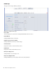
To set the CAN ID in range 0–15:
1 Set SW1-2 to OFF.
2 Use the CAN Rotary Switch to set the CAN ID.
To set the CAN ID in range 16–31:
1 Set SW1-2 to ON.
2 Use the CAN Rotary Switch to set the CAN ID.
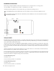
To avoid damaging analog circuits, install a master sync source module in a red reserved slot before applying AC power.
To use the MM935 in master mode in the IO93 or IO94 Frames, insert the MM935 into a red reserved slot and remove all other
sync modules from the frame.
MM935 installation diagram
SW1-2SW1-1