
Specifications


Chapter 7: FC972 Remote 53
A Modular I/O frame can employ two methods for remote control and configuration:
• CAN remote controllers: Set the frame address using the CAN Address switches, available on either the FC972 Remote or
the SY983. Set the CAN Address on one of these modules only. The other module must be set to a non-active default value
to avoid conflicts. This older method of setting an explicit CAN Address is used only when employing a hardware CAN-BUS
remote controller to configure frames. In
• Web browser interface: In current systems, the frame address is determined by the IP Address assigned with the FC972 Re-
mote. The CAN Address switches on the FC972 Remote and the SY983 modules must be set to non-active default values to
avoid conflicts.
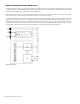
DEV 0 – DEV 2
These switches set the frame’s overall CAN Address for legacy systems utilizing a CAN remote controller. In systems utilizing the
web browser interface, DEV 0 – DEV 2 must all be set to ON (right position).
CAN-TERM
The CAN bus must be terminated once on either the SY983 or the FC972.
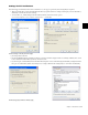
Network Address Configurations
The FC972 and a web browser interface provides the network to connect and configure a Modular I/O frame and its modules.
Since all Modular I/O frames require a web browser interface to enter module settings, configuring the FC972 Remote is a vital
part of the installation procedure.
Microphone Preamp Control
The AD914 is controlled by System 5 and Max Air consoles by connecting the frame’s FC972 Remote network port to the
System 5/Max Air network switch. The console surface controls the mic settings (i.e., gain, +48 V phantom power, high-pass fil-
ter, etc.), which are saved to and recalled from console Title files.
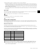
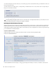
For proper console mic control, the correct frame address must be used, which is determined by the IP Address of the installed
FC972 remote. The following table shows addresses used by the system. The FC972 network Gateway setting is 192.168.0.1 in all
cases (the address of the console’s system computer).
These switches appear on the SY983 and must be set to non-active state on that module as well.
Do not terminate the CAN bus twice.
Console Mic Control Port TCC (ML530) Frame IP Address
Mic Control Port 1 TCC2 192.168.0.150/255.255.255.0
Mic Control Port 2 TCC3 192.168.0.151/255.255.255.0
Mic Control Port 3 TCC4 192.168.0.152/255.255.255.0
Mic Control Port 4 TCC5 192.168.0.153/255.255.255.0
Mic Control Port 5 TCC6 192.168.0.154/255.255.255.0
Mic Control Port 6 TCC7 192.168.0.155/255.255.255.0
Mic Control Port 7 TCC8 192.168.0.156/255.255.255.0
Console mic control ports may be used by any combination of Modular I/O Mic Pre frames or ML530 Mic-Line Interfaces (con-
trolled with a TCC serial control interface). Do not double-assign a mic control port by connecting an ML530 to a TCC control
line and a Modular Frame addressed to that port’s equivalent IP Address. For more information about TCC control, see the
System 5 or Max Air Operational Manuals.