
Specifications


Chapter 3: IO93 Modular Frame 31
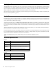
Control Bus
Each frame must be fitted with an FC972 Remote to externally configure all modules (except analog line in/out and WC984) and
control mic preamps remotely using a web browser or console. Install only one FC972 per frame and up to two SY983s (for re-
dundant operation, differentiated by Master/Slave setting).
A Module’s system ID consists of the Frame ID + module CAN ID. The Frame ID is determined by the FC972’s IP Address/Sub-
net/Host Address. The FC972 must be assigned a unique IP Address based on the frame’s role within the system. A CAN ID must
be set for each externally controllable module. Most modules have 32 CAN ID settings available but the AD914 Remote Mic Pre-
amp has 16.
The FC972 and SY983 have default module CAN IDs that do not interfere with those of other modules. The internal CAN bus
must be terminated once per frame, either on the FC972 or SY983.
Using the CAN Address switches on the FC972 or SY983 is an older method of setting the Frame ID. An explicit CAN Address must
be set only when employing a hardware CAN-BUS remote controller to configure frames. In System 5, the Frame ID is set with
the FC972's IP Address for configuration using a web browser interface.
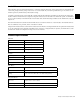
Technical Specifications
Frame Size
Depth 320 mm
Rack Space 3 RU
Front plane Module Space 72 HP (18 single-width slots)
Rear plane Module Space 76 HP (19 single-width slots)
Weight ~5.3 kg
AC Power
Power Supplies Dual redundant
Input 100
–240 VAC 50/60 Hz auto-sensing
Output 13 A @ 5 VDC
Connectors 2 IEC
Audio Busses
Front Plane 32 audio busses
Rear Plane 32 audio busses
Linking
Front and rear plane audio busses may be linked using DIP switches
on the interconnect PC board (some disassembly required)
Sync/Control Busses
Sync Slots
Four reserved slots for master sync source (4 HP each) on rear plane
(may be used for other modules)
Sync Linking Common sync bus, linked between backplanes
Control Bus Common CAN bus, linked between backplanes