
Specifications


Modular I/O Configuration Guide132
Installation Considerations
To initialize module parameters to their factory default values, press INIT during power up.
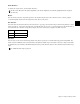
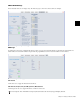
SW1-1 Functions
SW1-1 has four DIP switches that enable/disable BUS-EN and help set the CAN ID. SW1-1C and SW1-1D are unused. To set a switch
ON, move it to the right position.
Setting BUS-EN
The output configuration is taken from the non-volatile memory.
• SW1-1 ON connects the outputs to the audio busses on power up.
• SW1-1 OFF disconnects the module outputs from the audio busses on power up.
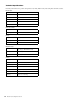
Setting the CAN ID
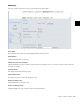
Each frame must be fitted with an FC972 Remote to externally configure all modules (except analog line in/out and WC984) and
control mic preamps remotely using a web browser. Install only one FC972 per frame and up to two SY983s (for redundant op-
eration, differentiated by Master/Slave setting).
A Module's system ID consists of the Frame ID + module CAN ID. The Frame ID is determined by the FC972’s IP Address/Sub-
net/Host Address. The FC972 must be assigned a unique IP Address based on the frame’s role within the system. A CAN ID must
be set for each externally controllable module. Most modules have 32 CAN ID settings available but the AD914 Remote Mic Pre-
amp has 16.
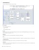
The FC972 and SY983 have default module CAN IDs that do not interfere with those of other modules. The internal CAN bus
must be terminated once per frame, either on the FC972 or SY983.
To avoid damaging analog circuits, install a master sync source module in a red reserved slot before applying AC power.
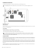
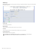
DE901 installation diagram
To avoid audio bus conflicts when installing or replacing a module and the configuration is unknown, disable the output bus
drivers by setting BUS-EN = OFF before inserting it. If all settings are done remotely and the unit fits into the frame’s bus
assignment scheme, remove it and set BUS-EN = ON.
SW1-1