
Specifications


Modular I/O Configuration Guide104
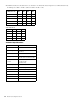
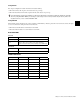
OUTPUT LEVEL Switches: Use the table below to set switches 1–4 to match the selected output level to 0 dBFS (full scale level).
For Example: Set 0 dBFS = +24 dB to achieve -20 dBFS = +4 dBU = 0 VU.
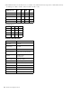
Technical Specifications
Analog Level
0 dBFS (full scale)
SW1 SW2 SW3 SW4
+15 dBU OFF OFF OFF OFF
+18 dBU OFF OFF OFF ON
+21 dBU OFF OFF ON OFF
+24 dBU OFF ON OFF OFF
+28 dBU ON OFF OFF OFF
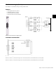
15 Pin D-Sub Pinout
Signal + GND -
Input 1 9 2,10 1
Input 2 11 4, 12 3
Input 3 6 5 13
Input 4 8 7, 14 15
Resolution 24 bit
Sample Rate 32
–96 kHz
Dynamic Range
112 dB (RMS)
117 dB (A)
THD+N <0.002% @ maximum output level
Frequency Response
48 kHz: 20 Hz – 20 kHz (
0,5 dB)
96 kHz: 20 Hz – 40 kHz (
0,5 dB)
Crosstalk
>110 dB (1 kHz)
>105 dB (20 kHz)
>90 dB (40 kHz)
Maximum Output Level 15
–28 dBu @ 0dBFS
Output Impedance 60 , floating balanced
Connector 15-pin D-Sub, female panel
Backplane Connector DIN41612, 64-pin, a+b, male
Power Supply +5 VDC
Consumption ~650 mA
Dimensions 3 RU, 4 HP (1 slot)