Modular I/O Configuration Guide
Legal Notices This guide is copyrighted ©2011 by Avid Technology, Inc., with all rights reserved. Under copyright laws, this guide may not be duplicated in whole or in part without the written consent of Avid.
Contents Part I Introduction to Modular I/O Chapter 1. Introduction . . . . . . . . . . . . . . . . . . . . . . . . . . . . . . . . . . . . . . . . . . . . . . . . . . . . . . . . . . . . . . . . . . . . . . . . . . . 7 Frame Specification . . . . . . . . . . . . . . . . . . . . . . . . . . . . . . . . . . . . . . . . . . . . . . . . . . . . . . . . . . . . . . . . . . . . . . . . . . . 7 IO93 Double-Sided Frame . . . . . . . . . . . . . . . . . . . . . . . . . . . . . . . . . . . . . . . . . . . . . . .
Part III Modules Chapter 6. Synchronization Modules . . . . . . . . . . . . . . . . . . . . . . . . . . . . . . . . . . . . . . . . . . . . . . . . . . . . . . . . . . . . . . . 41 SY983 Sync HD . . . . . . . . . . . . . . . . . . . . . . . . . . . . . . . . . . . . . . . . . . . . . . . . . . . . . . . . . . . . . . . . . . . . . . . . . . . . . . 41 WC984 4ch WCLK Out . . . . . . . . . . . . . . . . . . . . . . . . . . . . . . . . . . . . . . . . . . . . . . . . . . . . . . . . . . . . . . . . . . . . .
Part I: Introduction to Modular I/O
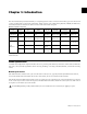
Chapter 1: Introduction The Avid Modular I/O system adds flexibility to configuring System 5 audio converters. Three frame types can be fitted with a variety of I/O modules to meet client requirements. Frame controller, Sync, MADI, Analog Mic/Line, AES/EBU, De-Embedder, and Dolby modules are available. The table below lists all modules in their categories.
Control Configuration Each frame must be fitted with an FC972 Remote to externally configure all modules (except analog line in/out and WC984) and control mic preamps remotely using a web browser or console. Install only one FC972 per frame and up to two SY983s (for redundant operation, differentiated by Master/Slave setting). Frame and Module Addresses A Module's system ID consists of the Frame ID + module CAN ID. The Frame ID is determined by the FC972’s IP Address/Subnet/Host Address.
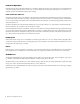
IO93 Double-Sided Frame The IO93 Double-Sided Frame is a 3RU frame with redundant PSU and two backplanes. Master sync source module(s) must be installed in one (or two) of the four red slots in the rear plane near the power outlet before applying AC power. Spare red slots may be used for other modules. Top view of IO93 frame layout with red slots reserved for Master sync source modules IO93 Frame Parameters Master Sync Source The IO93 frame consists of one sync zone that requires one master sync source.
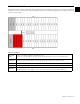
IO94 Stagebox Frame The IO94 Stagebox Frame is a 3RU frame with redundant PSU and a single backplane. It is ideally suited for stagebox applications and local I/O. Master sync source module(s) must be installed in one (or two) of the four red slots in the rear plane near the power outlet before applying AC power. Spare red slots may be used for other modules.
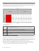
IO95 Multi-Zone Frame The IO95 Multi-Zone is a 3RU frame with redundant PSU and two backplanes. The frame is divided into five discrete audio/sync zones. The IO95 accommodates applications that use multiple I/O streams, each referenced to a separate sync source. For example, several Dolby-E encoder/decoders can be fitted into one IO95, each in its own audio/sync zone and referenced to separate sync sources.
Frame and Module Summaries Modular I/O Frame Summary Model Type Sync Backplane Space Power at 5 VDC Audio Busses IO93 Double-Sided Single sync zone Rear: 19 slots Front: 18 slots 13 A Rear: 32 busses Front: 32 busses linked or discrete IO94 Stagebox Single sync zone 19 slots 20 A 32 audio busses IO95 Multi-Zone Five discrete audio/ sync zones Zones 1–4: 6 slots Zone 5: 13 slots 13 A 5 discrete audio/sync zones 32 busses each Modular I/O Module Summary Model Type Connectors Audio B
Chapter 2: Typical Frame Configurations This chapter describes three typical frame configurations: • Digital I/O in IO94 Frame with redundant fiber connection • Stagebox I/O in IO94 Frame with console-side I093 Frame with two redundant fiber interfaces • I095 Multi-Zone Frame with discrete sync with Dolby® E Encoder These are useful examples to consult as you consider your own system configuration.
Synchronization To configure the frame for synchronization: 1 To avoid damaging analog circuitry, make sure the AC power is off before beginning the installation. 2 Install SY983 Sync HD #1 in a red reserved slot and set as Master. 3 Install SY983 Sync HD #2 in a red reserved slot and set as Slave. Control To configure remote control, use the FC972 Remote to set the following parameters: 1 Set the IP Address range to 192.168.0.157~159/255.255.255.0 2 Set the Gateway to 192.168.0.
Power The IO94 Frame has a maximum power capacity of 20 A @ 5 VDC. Each module’s power consumption and total power are listed in the table below. IO94 Frame Power Consumption Module Quantity Power (A) Subtotal (A) SY983 2 .30 .60 FC972 1 .30 .30 MM935 2 .36 .72 DD915 6 1.00 6.00 DE901 2 .50 1.00 HD944 6 .60 3.60 Total (A): 12.
Audio Routing The table below shows all module routing for the IO94 Frame with Digital I/O configuration. To connect the IO94 to the console, make the following MADI connections: 1 Connect MM935 #1 MADI Out to Console MADI In. 2 Connect MM936 #2 MADI Out to Console MADI In. 3 Connect Console MADI Out to MM935 #1 MADI In.
Remote Stageboxes with Redundant Fiber Connection Features • Remote IO94 Stagebox with 48 mic inputs and 16 line outputs • Redundant MADI-over-fiber audio connection • Console-side IO93 Frame with two redundant fiber interfaces • Console-side IO93 Frame local I/O with 24 line inputs and 32 line outputs Red outline shows master sync source modules for IO94 (MM936) and IO93 (SY983) Chapter 2: Typical Frame Configurations 17
Synchronization To configure each frame for synchronization: 1 To avoid damaging analog circuitry, make sure the AC power is off before beginning the installation. 2 Install the MM936 MADI in a reserved slot in the IO94 Frame and set it as Master. 3 Install the SY983 in a reserved slot in the IO93 Frame and set it as Master. Control To set up remote control for the IO94 and IO93 Frames: 1 Set the FC972 Remote to IP Address range: IO94: 192.168.0.150~156/255.255.255.0 IO93: 192.168.0.157~159/255.255.255.
IO93 Frame Module CAN ID MM935 #1 0 MM935 #2 1 MM935 #3 2 MM936 #1 3 MM936 #2 4 Power The IO94 Stagebox has a maximum power capacity of 20 A @ 5 VDC. The IO93 Frame has a maximum power capacity of 13 A @ 5 VDC. Individual module and total frame power consumption are summarized in the tables below. IO94 Stagebox Module Power Consumption Module Quantity Power (A) Subtotal (A) FC972 1 .30 .30 MM935 1 .36 .36 AD914 12 1.30 15.60 DA923 4 .65 2.60 Total (A): 18.
Audio Routing All audio routing between modules for the IO94 and IO93 Frames is shown in the two tables that follow. Follow the steps below to make Frame-to-Frame and Frame-to-console connections. To connect the modules in Stagebox #1: 1 Connect IO94 Stagebox #1 MM936 MADI Out to IO93 Frame MM936 #1 MADI In (fiber). 2 Connect IO93 Frame MM936 #1 MADI Out to IO94 Stagebox #1 MM936 MADI In (fiber). 3 Connect Console MADI Out to MM935 #1 MADI In. 4 Connect IO93 MM935 #1 MADI Out to Console MADI In.
IO94 Stagebox Module Audio Routing Since Stagebox #2 is the same as Stagebox #1, only Stagebox #1 routing is shown.
IO93 Frame Module Audio Routing IO93 Audio Routing: Stagebox Fiber Interface Routing Source Module Signal Audio Bus Channels Side Bus Destination Mode Module Signal Channels MM936 #1 MADI In 1–8 front S1 8ch MM935 #1 MADI Out 1–8 MM936 #1 MADI In 9–16 front S2 8ch MM935 #1 MADI Out 9–16 MM936 #1 MADI In 17–24 front S3 8ch MM936 #1 MADI Out 17–24 MM936 #1 MADI In 25–32 front S4 8ch MM936 #1 MADI Out 25–32 MM936 #1 MADI In 33–40 front S5 8ch MM936 #1 MADI Ou
IO93 Audio Routing: Stagebox Fiber Interface Routing MM935 #3 MADI In 13/14 back S26 2ch DA923 #4 Line Out 1/2 MM935 #3 MADI In 15/16 back S25 2ch DA923 #4 Line Out 3/4 MM935 #3 MADI In 17/18 back S24 2ch DA923 #5 Line Out 1/2 MM935 #3 MADI In 19/20 back S23 2ch DA923 #5 Line Out 3/4 MM935 #3 MADI In 21/22 back S22 2ch DA923 #6 Line Out 1/2 MM935 #3 MADI In 23/24 back S21 2ch DA923 #6 Line Out 3/4 MM935 #3 MADI In 25/26 back S20 2ch DA923 #7 Line
Dolby E Encoder with Discrete Sync in IO95 Multi–zone Frame In most cases, Dolby E Encoders may be integrated into any standard frame configuration. However, the Dolby E stream sometimes uses external sync that is asynchronous with the console sync. Each Dolby E Encoder must then be paired with its own sync module isolated from console sync. Audio signals feeding the Dolby E encoders must also be decoupled from console sync.
Control To set up remote control for the IO95 Frame, use the FC972 Remote to configure the following parameters: 1 Set the IP Address range to 192.168.0.157~159/255.255.255.0. 2 Set the Gateway to 192.168.0.1 for configuration by console system computer. See “FC972 Remote” on page 49 for details. This frame does not contain mic preamps so IP Address range 192.168.0.150~156 is skipped. Module CAN IDs Set the CAN ID of each module to match the table below.
MADI Routing The table below shows all module routing for this configuration.
Part II: Frames
Chapter 3: IO93 Modular Frame The IO93 is housed in a 3-RU, RF-shielded, 19-inch modular chassis.
Cooling Install the IO93 with at least 1 RU of space above and below the frame and unrestricted airflow on the sides. Master Sync Module Make sure to install a master sync module in one of the red reserved slots before applying AC power. This is typically an SY983 Sync module, but the following other modules may be used as a master sync module when set to Master mode: MM935 MADI, MM936 MADI, DD915 8ch AES I/O, DD916 8ch AES I/O, and HD944 16ch De-embedder.
Control Bus Each frame must be fitted with an FC972 Remote to externally configure all modules (except analog line in/out and WC984) and control mic preamps remotely using a web browser or console. Install only one FC972 per frame and up to two SY983s (for redundant operation, differentiated by Master/Slave setting). A Module’s system ID consists of the Frame ID + module CAN ID. The Frame ID is determined by the FC972’s IP Address/Subnet/Host Address.
Modular I/O Configuration Guide
Chapter 4: IO94 Stagebox Frame The IO94 is housed in a 3-RU, RF-shielded, 19-inch modular chassis designed specifically for stagebox applications. Features • Two power supplies in redundant mode with 20 A capacity @ 5 VDC • One RP991 Dual Power Inlet with mains filter and switch • Rear plane card installation • Common sync bus • Common control bus • External dimensions in accordance with DIN 41494: depth = 320 mm • Chromated aluminum side panels; aluminum cross extrusions; 0.
Cooling Install the IO94 with at least 1 RU of space above and below the frame. There should be unrestricted airflow on the sides and over PSU heatsinks. Master Sync Module Make sure to install a master sync module in one of the four red reserved slots (left side of frame) before applying AC power.
Technical Specifications Frame Size Depth 320 mm Rack Space 3 RU Module Backplane Space 76 HP (19 single-width slots) Weight ~5.
Modular I/O Configuration Guide
Chapter 5: IO95 Multi-Zone Frame The IO95 Multi-Zone Frame is a 3RU frame with redundant PSU and two backplanes. The frame is divided into five discrete audio/sync zones. The IO95 accommodates applications that use multiple I/O streams, each referenced to a separate sync source. For example, several Dolby-E encoder/decoders can be fitted into one IO95, each in its own audio/sync zone and referenced to separate sync sources.
Audio/Sync Zones The IO95 frame consists of five discrete sync zones, each requires its own master sync source. Although this is typically an SY983 Sync HD module (or two SY983s configured in redundant sync mode), an I/O module with Master mode may serve as a master sync source but not in conjunction with an SY983 in the same zone. Examples of modules with Master mode are MM935 MADI, MM936 MADI, DD915 8ch AES I/O, DD916 8ch AES I/O, and HD944 16ch De-embedder.
Part III: Modules
Chapter 6: Synchronization Modules SY983 Sync HD The SY983 is the standard sync module for a modular I/O frame. Features • Internal sync: 44.
Installation Considerations Frames employ the CAN-bus for internal communication. Each module must have a unique System ID that consists of the Frame ID + module CAN ID. The Frame ID is determined by the FC972’s IP Address/Subnet/Host Address. The FC972 must be assigned a unique IP Address based on the frame’s role within the system. A CAN ID must be set for each externally controllable module. Most modules have 32 CAN ID settings available but the AD914 Remote Mic Preamp has 16.
DEV X The DEV X switch accommodates legacy systems requiring a CAN remote to communicate with up to 16 modules spread across two frames. In single SY983 frames, DEVX has no effect. In redundant SY983 frames, the DEVX switch must be set to the same position in both modules. TERM The CAN bus must be terminated only once in a frame on either the SY983 or on an FC972 Remote. Do not terminate the CAN bus twice. SLAVE For fail-safe operation, a frame may be equipped with a second (redundant) sync module.
DEVICE Page SY983 Web Configuration Device page Slave LED The Slave status is displayed on the left. The red Slave LED indicates this is a slave module in fail-safe operation. Restart Module Clicking RESTART initiates a warm start. Initialize and restore factory defaults Clicking INITIALIZE restores factory defaults. Controller Version Displays the module’s firmware version. Backup All Settings to File Clicking BACKUP stores the current settings to file on the configuration computer.
PARAMETERS Page This page configures sync source parameters. Web Configuration Parameters page Sync Source Setting the sync source here overwrites the settings made on the front panel’s rotary switch. Select from the following Sync Sources: Internal: 44.1, 48, 96 kHz. External: AES, WCLK, Video. GPI Page This page sets the sync source with GPI. GPO Page This page provides tally for the selected sync source.
Technical Specification Internal and External Synchronization Internal Audio Sync 44.1, 48, 96 kHz External Sync Input BNC, 75 External Sync Types Video (BB, CS, TLS), Wordclock, AES/EBU sync Video Synchronization Types Blackburst, Composite, Tri-level Level Blackburst/composite: 0.5–1 Vpp Tri-level: +/- 0.3 V Formats PAL/NTSC/HDTV Rates 525, 625 1080i/50/59.94/60 720p/50/59.94/60 1080p/23.98/24/25/29.97/30/50/59.
WC984 4ch WCLK Out The WC984 is a wordclock synchronization output module for Modular I/O systems. Features • Word Clock outputs buffered four times • Frame sync bus provides the sync source • Sync output for sync-to-MADI frames WC984 front panel (left) and block diagram (right) Installation Considerations The WC984 requires no settings. Specifications WC984 Specifications Wordclock Output 44.
Modular I/O Configuration Guide
Chapter 7: FC972 Remote The FC972 Remote is an essential module to configure externally controlled modules and remotely control mic preamps using a web browser interface. Each frame type contains a single control bus and requires one FC972 to be installed in any frame position. During installation, be careful to adhere to the correct IP Address and CAN Bus termination instructions.
Installation Considerations MAC Address Default IP Address FC972 Module diagram The MAC address is printed on the label indicated in the figure above. The default IP address label is located on the Coldfire chip of the controller module and on the module’s front panel.
Connector Pinouts contacts Latch RJ45 cable shown from cable entry side RJ45 LAN Connector (NC for pins 4, 5, 7, 8) Pin # Signal 1 Tx + 2 Tx - 3 Rx + 6 Rx - RJ45 CAN Connector (NC for pins 3, 6, 7, 8) Pin # Signal 1 CAN-H 2 CAN-L 4 GND 5 GND 9-Pin D-Sub RS232 Connector Pin # Function 1 DCD 2 TxD 3 RxD 4 DTR 5 GND 6 DSR 7 CTS 8 RTS 9 N.C.
Front Panel Init Switch and Status LED The Status LED lights yellow while booting and green when operating. The Init button supports warm module restart or full reset of the module to factory defaults. To initialize the FC972 to factory defaults: 1 Press the Init button briefly. 2 After about 5 seconds the Status LED lights yellow. 3 Press and hold the Init button until the Status LED flashes three times. Rebooting the FC972 has no effect on audio processing.
A Modular I/O frame can employ two methods for remote control and configuration: • CAN remote controllers: Set the frame address using the CAN Address switches, available on either the FC972 Remote or the SY983. Set the CAN Address on one of these modules only. The other module must be set to a non-active default value to avoid conflicts. This older method of setting an explicit CAN Address is used only when employing a hardware CAN-BUS remote controller to configure frames.
Modular I/O frames without AD914 4ch Mic Inputs may also be connected to the console network, which lets the console's system computer configure modules. In this case, use an IP address in the range 192.168.0.157–159 to reserve Console Mic Control Port IP addresses for future expansion. Modular I/O frames that do not contain AD914 4ch Mic Inputs may optionally connect to a separate facility network for configuration and use an appropriate address for that network.
3 Open a browser (IE7. Firefox 3.0 or higher) and enter the FC972’s IP address in the URL field (i.e., http://10.110.134.142). 4 Click on the wrench tool on the CONTROLLER field. This opens the FC972’s SYSTEM CONFIG page. wrench tool Frame Controller Overview page 5 Enter the proper NETWORK settings. NETWORK settings 6 Select CHANGE NETWORK CONFIGURATION. 7 Reboot the FC972. REBOOT CONTROLLER tab 8 Reconfigure the PC’s network address to communicate with the FC972 if necessary.
Remote Configuration using a Web Browser Modular I/O frames are remote controlled and configured through a network connection between the FC972 and a PC running a common web browser. This Ethernet-based external access is maintained by a dedicated 32-bit communication processor in the FC972 that runs an HTTP server, a UDP server, and an SNMP agent. After launching the browser on the PC and entering the frame’s IP address, all data including GUI is served out from the FC972 to the browser window.
Settings For IE 7 And Firefox 3 The FC972 supports GUI functions for IE 7.x and Firefox 3.x. For proper operations, these settings may be required: • The browser must allow cookies from Modular I/O units. Pay special attention to settings of third-party tool bars (like Yahoo) which may overwrite the browser’s settings. • To receive files (i.e., frame backup) from the Frame Controller, select the security option: Tools > Internet Options > zone = Internet > Custom level … > Downloads.
• Declare IE (and/or FireFox) as an exception for the Windows Firewall to maintain proper UDP data transfer from and to the JAVA applet. • If you notice security issues, you may use the UDP PORT RANGE configuration (see “Setting the UDP Port Range” on page 59) to limit the UDP port numbers instead of making an exception for all incoming network connections. • Disable the browser’s caching features. The FC972’s web pages are designed to operate in LANs.
Activating the Security Feature The FC972 Remote offers a three-tier security scheme: • Viewers can only see status information and level displays. • Operators have Viewer privileges and can also load presets. • Administrators have Operator privileges and can also set up frames, change module parameters, and write presets. 1 Select Password checking enabled to activate this feature. 2 Reboot the Frame Controller.
To connect from different PCs to the same device, use one UDP port per device because different PCs open a different IP socket connection for the same device. To connect from one PC to different devices, a unique UDP port number must be set for every remote device so assign a range of UDP ports for the Frame Controller.
4 Click the START UPDATE NOW button. A progress bar appears when the update process starts. The controller uploads the image file from the PC into its memory, erases the flash memory, and burns the new image. A dialog appears when finished. 5 Click OK and the browser reloads the website from the FC972 Remote. If you still see old firmware version number, flush the browser content by deleting temporary internet files and cookies, and connect with the frame.
2 Click SAVE LICENSE INFO and an XML file is generated that should be saved and sent to Avid sales/support. Avid returns a License File that must be uploaded to the FC972 Remote. 3 Click the SEARCH button to navigate to the file. 4 Click APPLY LICENSE NOW. We recommend updating modules before applying the license key file to the frame because some license features require the latest firmware.
SNMP Operation The FC972's SNMP agent polls the system and generates status information. Modules are polled continuously and the status information is condensed for the entire frame. An external monitoring tool (SNMP Manager) may poll the SNMP agent based on the Modular I/O Audio MIB (Management Information Bases). The MIB and associated document can be received upon request. The SNMP manager can also sit and wait to receive Traps from the SNMP agent and poll the frame afterward.
Using a slider to change parameter values Error Monitoring When an upstream error condition (i.e., processor module) that results in signal loss at the embedder input is detected, the module switches to an alternative bus for fail-safe operation. The alternative bus can be a similar signal bypassing the processing module (i.e., processor input signal), or an alternate audio signal (i.e., pre-recorded announcement).
Monitoring the Processing Status of a Processing Module The most important audio processing module parameter is its momentary gain, which is permanently changed by an adaptive dynamic process like LevelMagic™. If this gain persists too long at one end of its working range, the processing parameters should be checked. The definition of the Level Magic persistent condition is: The low-pass weighted average gain of the process is equal to or greater than the Leveler max Gain.
Technical Specifications Controller Module Microcontroller MCF8250 Coldfire FLASH 8 Mbyte RAM 16 Mbyte RTC DS 1306 OS eCos Front Panel External Connectors LAN (RJ45) 10/100 Mbit Ethernet RS232 (9-pin D-Sub) Controller serial interface CAN (RJ45) CAN 1.1 (125 kBit/s) Default Settings IP address 10.110.xxx.yyy where xxx and yyy is derived from the MAC address of the Ethernet interface Subnet Mask 255.255.0.
Chapter 8: MADI Modules MM935 MADI In/Out (Coaxial) The MM935 is an I/O interface for MADI multichannel audio signals.
Installation Considerations Switch 1 helps configure the MM935’s master mode and CAN ID. To set a switch ON, move it to the up position. To set the MM935 to clock master mode, set SW1-1 to ON. Otherwise, set it to OFF. To initialize all module parameters to factory default values, press the INIT button during power-on. To avoid damaging analog circuits, install a master sync source module in a red reserved slot before applying AC power.
Remote Configuration using a Web Browser The MM935 is configured using a web browser interface, which requires fitting an FC972 Remote in the frame. See “FC972 Remote” on page 35. PRESET Page Each Preset includes the parameters of the transmitter and the receiver. Eight User Presets are available which can be changed manually or by GPI. MM935 Web Configuration Presets page Load Preset Selecting a preset from the menu and pressing LOAD NOW loads that preset from the module memory.
DEVICE Page This page sets and displays MM935 parameters. MM935 Web Configuration Device page Device Name This field displays the current name. Clicking CHANGE NAME renames the device. Restart Module Clicking RESTART initiates a warm start. Initialize and restore factory defaults Clicking INITIALIZE restores factory default settings. Controller Version Displays the module’s controller firmware version. FPGA Version Displays the module’s FPGA firmware version.
SETUP Page This page sets up MADI and error processing parameters. MM935 Web Configuration Setup page MADI Bypass Selecting Active bypasses MADI processing. MADI Input No function in this module. Error Processing Used for remote system monitoring. Select Active to enable global bus error detection. Error Mask (BUS) Selecting these turns on error detection for individual busses (S1–S32). Error detection must be turned OFF for busses not in use to prevent bad module status message.
RECEIVERS Page This page routes MADI input signals to the frame’s audio busses. MM935 Web Configuration Receivers page 8 Channel Mode (TDM) Groups of eight adjacent MADI input channels can be routed to a single audio bus (S1–S32) or OFF. 2 Channel Mode Pairs of adjacent MADI input channels can be routed to a single audio bus (S1–S32) or OFF. Enable C8000 Bus Driver Selecting this option enables all 32 bus drivers.
TRANSMITTERS Page This page connects the frame’s audio busses to MADI outputs. MM935 Web Configuration Transmitters page Number of Channels The number of audio channels per MADI stream can be set to 56 or 64. Ensure the equipment connected is set to the same number. 8 Channel Mode (TDM) An audio bus (S1–32) can be connected to a group of eight adjacent MADI output channels. Ensure the source signal on the audio bus is also set to 8 Channel Mode.
GPI Page This page sets up frame-wide GPI numbers to trigger dedicated module functions. If a GPIO system module detects a GPI input, it puts the associated GPI number on the CAN bus. Each frame module watches for these GPI numbers and performs the programmed action if it reads that number on the CAN bus. Do not assign the same GPIO numbers to different functions because this incorrectly triggers multiple functions.
GPO Page This page sets up frame-wide GPO numbers to trigger a dedicated GPO (Tally) of a GPIO module. MM935 Web Configuration GPO page Do not assign the same GPIO numbers to different functions because this incorrectly triggers multiple functions. Preset 1–8 A GPO output can be entered that triggers when a Preset is recalled. MADI Bypass On A GPO output can be entered that triggers when MADI Bypass On is enabled. Lock A GPO output can be entered that triggers when the module is sync locked.
Technical Specifications MADI Interface Standard AES 10 (2003) Connection 75 BNC Signal Level 800 mV 10% Audio Data Format 24-bit transparent for C- and U-Bit according to AES3 Audio Sample Rate 48 kHz: 64 channels 96 kHz: 32 channels General Specifications Backplane Connector DIN41612, 64-pin, a+b, male Power Supply +5 VDC Consumption ~360 mA Dimensions 3 RU, 4 HP (1 slot) Ambient 10°C to 40°C Humidity 90%, non-condensing 76 Modular I/O Configuration Guide
MM936 MADI In/Out (Redundant Fiber) The MM936 is an I/O interface for MADI multichannel audio signals.
Installation Considerations SW1 helps configure the MM936’s master mode and CAN ID. To set a switch ON, move it to the up position. To set the MM936 to clock master mode, set SW1-1 to ON. Otherwise, set it to OFF. To initialize all module parameters to factory default values, press the INIT button during power-on. To avoid damaging analog circuits, install a master sync source module in a red reserved slot before applying AC power.
Remote Configuration using a Web Browser The MM936 is configured using a web browser interface, which requires fitting an FC972 Remote in the frame. See “FC972 Remote” on page 35. PRESET Page Each Preset includes the parameters of the transmitter and the receiver. Eight User Presets are available which can be changed manually or by GPI. MM936 Web Configuration Presets page Load Preset Selecting a preset from the menu and pressing LOAD NOW loads that preset from the module memory.
DEVICE Page This page manages basic settings for the MM935. MM936 Web Configuration Device page Device Name This field displays the current name. Click CHANGE NAME to rename the device. Restart Module Clicking RESTART initiates a warm start. Initialize and restore factory defaults Clicking INITIALIZE restores factory default settings. Controller Version This displays the module’s controller firmware version. FPGA Version This displays the module’s FPGA firmware version.
SETUP Page This page sets up MADI and error processing parameters. MM936 Web Configuration Setup page MADI Bypass Selecting Active bypasses MADI processing. MADI Input Selecting Input 1 or Input 2 manually activates that input. Selecting Auto automatically switches over from Input 1 to Input 2 if Input 1 fails due to loss of signal. Error Processing This is used for remote system monitoring. Select Active to enable bus error detection.
RECEIVERS Page This page routes MADI input signals to the frame’s audio busses. MM936 Web Configuration Receivers page 8 Channel Mode (TDM) A group of 8 adjacent MADI input channels can be routed to a single audio bus (S1–S32) or OFF. 2 Channel Mode Pairs of adjacent MADI input channels can be routed to a single audio bus (S1–S32) or OFF. Enable C8000 Bus Driver Selecting this option enables all 32 bus drivers.
TRANSMITTERS Page This page connects the frame’s audio busses to MADI outputs. MM936 Web Configuration Transmitters page Number of Channels Sets the number of audio channels per MADI stream to 56 or 64. Ensure the equipment connected is set to the same number. 8 Channel Mode (TDM) An audio bus (S1–32) can be routed to a group of 8 adjacent MADI output channels. Ensure the source signal on the audio bus is also set to 8 Channel Mode.
GPI Page This page sets up frame-wide GPI numbers to trigger dedicated module functions. If a GPIO system module detects a GPI input, it puts the associated GPI number on the CAN bus. Each frame module watches for these GPI numbers and performs the pre-programmed action if it reads that number on the CAN bus. Do not assign the same GPIO numbers to different functions because this incorrectly triggers multiple functions.
GPO Page This page sets up frame-wide GPO numbers to trigger a dedicated GPO (Tally) of a GPIO module. MM936 Web Configuration GPO page Do not assign the same GPIO numbers to different functions because this incorrectly triggers multiple functions. Preset 1–8 A GPO output can be entered to trigger when a Preset is recalled. MADI Bypass On A GPO output can be entered to trigger when MADI Bypass On is enabled. Lock A GPO output can be entered to trigger when the module is sync locked.
Technical Specifications MADI Interface Standard AES 10 (2003) Connections SC duplex x2 62.
Chapter 9: Mic/Line Analog Modules AD914 4ch MIC-In The AD914 is a four-channel microphone input interface.
Installation Considerations To initialize all module parameters to factory default values, press the INIT button during power-on. To avoid damaging analog circuits, install a master sync source module in a red reserved slot before applying AC power.
Configuration for Console Control The AD914 is controlled by System 5 and Max Air consoles by connecting the frame’s FC972 Remote network port to the System 5/Max Air network switch. Mic settings (gain, +48 V, high-pass filter, etc.) are controlled from the console surface. Settings are saved to console Title files and recalled when a Title is loaded. For proper console mic control, you must use the correct frame address which is determined by the IP Address of the installed FC972 remote.
Cabling The console Cabling feature maps a console’s mic preamp control port to the MADI input at which the mic’s audio appears. This means that the audio from a mic patched into an audio channel appears at that channel’s input along with relevant preamp controls on the channel’s strip. For more information on Cabling, see the System 5 or Max Air Guides. An ML530 Mic-Line Interface connects to a console mic control port using a TCC serial connection.
Remote Configuration using a Web Browser The MM936 is configured using a web browser interface, which requires fitting an FC972 Remote in the frame. See “FC972 Remote” on page 35. PRESET Page Each Preset includes the parameters of the transmitter and the receiver. There are eight User Presets, each can be changed manually or by GPI. AD914 Web Configuration Presets page Load Preset Selecting a preset from the menu and pressing LOAD NOW loads that preset from the module memory.
DEVICE Page This page configures device-specific parameters of the AD914. AD914 Web Configuration Device page Device Name This field displays the current name. Click CHANGE NAME to rename the device. Restart Module Clicking RESTART initiates a warm start. Initialize and restore factory defaults Clicking INITIALIZE restores factory default settings. Controller Version This displays the module’s firmware version. Backup all settings to File Clicking BACKUP stores all settings to file.
PARAMETERS Page The PARAMETERS Page enters mic settings manually. AD914 Web Configuration Parameters page Gain 0 dB, 10–65 dB. Line Selecting this option activates a 10-dB input attenuation pad. Mute Selecting this option mutes the selected input. Phantom Selecting this option turns 48 V phantom power on for the selected input. BUS ROUTING Page This page controls bus routing from the AD914.
GPI Page This page sets up frame-wide GPI numbers to trigger dedicated module functions. If a GPIO system module detects a GPI input, it puts the associated GPI number on the CAN bus. Each frame module watches for these GPI numbers and performs the pre-programmed action if it reads that number on the CAN bus. Do not assign the same GPIO numbers to different functions because this incorrectly triggers multiple functions.
GPO Page This page configures GPO events for the AD914. Do not assign the same GPIO numbers to different functions because this incorrectly triggers multiple functions. AD914 Web Configuration GPO page Preset 1–8 A GPO output can be set to trigger when a Preset is recalled.
Technical Specifications Analog Input Dynamic Range 110 dB (RMS) THD+N <0.09% @ maximum input level Equivalent Input Noise 126.
AD920 4ch Analog Line Input (XLR) The AD920 is a four-channel, analog, line input A/D interface. Features • 24-bit sigma-delta A/D-converter • 96 kHz maximum sample rate • Floating balanced analog inputs • Electrical isolation between channels AD920 front panel (left) and block diagram (right) Installation Considerations Bus Select Jumper 1/2: Routes line inputs 1/2 to the selected audio bus in 2-channel mode (S1–S32/OFF).
Input Level Switches: Use the table below to set switches 1–4 to match the selected input level to 0 dBFS (full scale level). For Example: Set 0 dBFS = +24 dB to achieve -20 dBFS = +4 dBU = 0 VU. Analog Level 0 dBFS (full scale) SW1 SW2 SW3 SW4 +15 dBU OFF OFF OFF OFF +18 dBU OFF OFF OFF ON +21 dBU OFF OFF ON OFF +24 dBU OFF ON OFF OFF +28 dBU ON OFF OFF OFF To avoid damaging analog circuits, install a master sync source module in a red reserved slot before applying AC power.
DA921 4ch Analog Line Output (XLR) The DA921 is a four-channel, analog, line output D/A interface. Features • 24-bit sigma-delta A/D-converter • Maximum sample rate: 96 kHz • Floating balanced analog inputs • Electrical isolation between channels DA921 front panel (left) and block diagram (right) Installation Considerations Bus Select Jumper 1/2: Routes line outputs 1/2 to the selected audio bus in 2-channel mode (S1–S32/OFF).
OUTPUT LEVEL Switches: Use the table below to set switches 1–4 to match the selected input level to 0 dBFS (full scale level). For Example: Set 0 dBFS = +24 dB to achieve -20 dBFS = +4 dBU = 0 VU. Analog Level 0 dBFS (full scale) SW1 SW2 SW3 SW4 +15 dBU OFF OFF OFF OFF +18 dBU OFF OFF OFF ON +21 dBU OFF OFF ON OFF +24 dBU OFF ON OFF OFF +28 dBU ON OFF OFF OFF Technical Specifications Resolution 24 bit Sample Rate 32–96 kHz Dynamic Range 112 dB (RMS) 117 dB (A) THD+N <0.
AD922 4ch Analog In (D-Sub) The AD922 is a four-channel, analog, line input A/D interface. Features • 24-bit sigma-delta A/D-converter • Maximum sample rate: 96 kHz • Floating balanced analog inputs • Electrical isolation between channels AD922 front panel (left) and block diagram (right) Installation Considerations AD922 installation diagram Bus Select Jumper 1/2: Routes line inputs 1/2 to the selected audio bus in 2-channel mode (S1–S32/OFF).
INPUT LEVEL switches: Use the table below to set switches 1–4 to match the selected input level to 0 dBFS (full scale level). For Example: Set 0 dBFS = +24 dB to achieve -20 dBFS = +4 dBU = 0 VU.
DA923 4ch Analog Out (D-Sub) The DA923 is a four-channel, analog, line out D/A interface. Features • 24-bit sigma-delta A/D-converter • 96 kHz maximum sample rate • Floating balanced analog inputs • Electrical isolation between channels DA923 front panel (left) and block diagram (right) Installation Considerations Bus Select Jumper 1/2: Routes the selected audio bus to line outputs 1/2 in 2-channel mode (S1–S32/OFF).
OUTPUT LEVEL Switches: Use the table below to set switches 1–4 to match the selected output level to 0 dBFS (full scale level). For Example: Set 0 dBFS = +24 dB to achieve -20 dBFS = +4 dBU = 0 VU.
Chapter 10: AES I/O and HD Modules DD915 8ch AES I/O (110 Ohm) The DD915 is an 8-channel AES I/O with four inputs and four outputs.
Installation Considerations To initialize the module parameters to factory default values, press the INIT button during power on. SW1-1 SW1-2 SW1-4 DD915 installation diagram SW1 Functions SW1 has four DIP switches that enable/disable BUS-EN, MASTER, and ID+16. SW1-3 is unused. To set a switch ON, move it to the up position. To avoid damaging analog circuits, install a master sync source module in a red reserved slot before applying AC power.
Setting BUS-EN The output configuration is taken from the non-volatile memory. • SW1-1 ON connects the outputs to the audio busses on power up. • SW1-1 OFF disconnects the module outputs from the audio busses on power up. To avoid audio bus conflicts when installing or replacing a module and the configuration is unknown, disable the output bus drivers by setting BUS-EN = OFF before inserting it.
Remote Configuration using a Web Browser The DD915 is configured using a web browser interface, which requires fitting an FC972 Remote in the frame. See “FC972 Remote” on page 35. OVERVIEW Page This page provides an overview of the frame’s modules. Click the wrench tool to open the configuration pages of that module.
DEVICE Page This page configures and displays device-specific DD915 parameters. DD915 Web Configuration Device page Device Name This field displays the current name. Click CHANGE NAME to rename the device. Restart Module Clicking RESTART initiates a warm start. Initialize and restore factory defaults Clicking INITIALIZE restores factory default settings. Controller Version This displays the module’s firmware version. Backup all settings to File Clicking BACKUP stores all settings to file.
Setup/Routing Page This page controls DD915 routing and setup parameters. DD915 Web Configuration Setup/Routing page Relay Bypass The AES I/Os provide a bypass relay for all eight channels, which may be turned off. With Relay Bypass On, the I/Os are in Relay Bypass mode. Relay Wait Time After Power Up The Relay Bypass is active as long as the module has no power. If power is turned on, the module waits this amount of time before the relays are engaged to disable Relay Bypass.
Enable Bus Driver Selecting this option turns on all module bus drivers (from tri-state mode). From C8000 Bus Output Mux The multiplex mode for incoming audio signals from the audio bus can be set to 2ch or 8ch.
GPO Page This page configures GPO events for the DD915. DD915 Web Configuration GPO page AES Input Error 1/2, 3/4, 5/6, 7/8 A GPO output can be set to trigger when an AES/EBU input error is detected on the selected channel pair. Do not assign the same GPIO numbers to different functions because this incorrectly triggers multiple functions.
DD916 8ch AES I/O (75 Ohm) The DD916 is a digital eight-channel AES I/O interface.
Installation Considerations To initialize the module parameters to factory default values, press the INIT button during power on. To set a switch ON, move it to the up position. SW1-1 SW1-2 SW1-4 DD916 installation diagram SW1 Options SW1 has four DIP switches that enable/disable BUS-EN, MASTER, and ID+16. SW1-3 is unused. To avoid damaging analog circuits, install a master sync source module in a red reserved slot before applying AC power.
Setting BUS-EN The output configuration is taken from the non-volatile memory. • SW1-1 ON connects the outputs to the audio busses on power up. • SW1-1 OFF disconnects the module outputs from the audio busses on power up. To avoid audio bus conflicts when installing or replacing a module and the configuration is unknown, disable the output bus drivers by setting BUS-EN = OFF before inserting it.
Remote Configuration using a Web Browser The DD916 is configured using a web browser interface, which requires fitting an FC972 Remote in the frame. See “FC972 Remote” on page 35. OVERVIEW Page This page provides an overview of the frame’s modules. Click the wrench tool to open the configuration pages of that module.
DEVICE Page This page configures device-specific DD916 parameters. DD916 Web Configuration Device page Device Name This field displays the current name. Click CHANGE NAME to rename the device. Restart Module Clicking RESTART initiates a warm start. Initialize and restore factory defaults Clicking INITIALIZE restores factory default settings. Controller Version Displays the module’s firmware version. Backup all settings to File Clicking BACKUP stores all settings to file.
SETUP/ROUTING Page This page configures setup and routing for the DD916. DD916 Web Configuration Setup/Routing page Relay Bypass The AES I/Os provide a bypass relay for all eight channels, which may be turned off. With Relay Bypass On, the I/Os are in Relay Bypass mode. Relay Wait Time After Power Up The Relay Bypass is active as long as the module has no power. If power is turned on, the module waits this amount of time before the relays are engaged to disable Relay Bypass.
AES Input Error Detection This option can be enabled to monitor the status of the AES/EBU inputs for signal presence and three detailed error types: Lock AES receiver lock status Validity AES3 validity bit detected Parity AES parity (data errors detection) Each AES input can be masked for error detection: Grey Error detection disabled Green No error detected/PCM audio Yellow No error detected/non audio (Dolby E, D) Red Indicates an error condition.
GPO Page This page configures GPO events for the DD916. DD916 Web Configuration GPO page Do not assign the same GPIO numbers to different functions because this incorrectly triggers multiple functions. AES Input Error 1/2, 3/4, 5/6, 7/8 Sets a GPO output to trigger when an AES/EBU input error is detected on the selected channel pair.
HD944 SDI-Demux (De-embedder) The HD944 is a 16-channel de-embedder. Features • BNC connectors: IN, THROUGH (active loop, re-clocked) • De-embedder: automatically detects HD/SD signal format; 16 channels out of 4 groups simultaneous; mono routing (8x2-ch) to audio busses.
Installation Considerations MODE Switches Push the MODE switches to the right to turn them ON or to the left to turn them OFF. MODE-1 MODE-2 MODE-3 MODE-4 HD944 installation diagram Setting BUS-EN The output configuration is taken from the non-volatile memory. • MODE-3 ON connects the outputs to the audio busses on power up. • MODE-3 OFF disconnects the module outputs from the audio busses on power up.
Setting the CAN ID Each frame must be fitted with an FC972 Remote to externally configure all modules (except analog line in/out and WC984) and control mic preamps remotely using a web browser. Install only one FC972 per frame and up to two SY983s (for redundant operation, differentiated by Master/Slave setting). A Module's system ID consists of the Frame ID + module CAN ID. The Frame ID is determined by the FC972’s IP Address/Subnet/Host Address.
Remote Configuration using a Web Browser The HD944 is configured using a web browser interface, which requires fitting an FC972 Remote in the frame. See “FC972 Remote” on page 35. OVERVIEW Page This page provides an overview of the frame’s modules. Click the wrench tool to open the configuration pages of that module.
PRESETS Page The HD944 has eight Presets, named PRE1 to PRE8 by default. The status area on the left shows the name of the active preset. When a preset parameter is changed, modified appears to the left of the preset name until it is saved. HD944 Web Configuration Presets page Name This field displays the Preset’s name. Click the name to enter a new name (four letters or less). Load Selecting a Preset name from the Load menu and clicking LOAD NOW loads a new Preset.
DEVICE Page The status area on the left shows the name of the active preset. When a preset parameter is changed, modified appears to the left of the preset name until it is saved. HD944 Web Configuration Device page Device Name This field displays current name. Click CHANGE NAME to rename the device. Restart Module Clicking RESTART initiates a warm start. Initialize and restore factory defaults Clicking INITIALIZE restores factory default settings.
DE-EMBEDDER Page This page sets de-embedding parameters for the HD944. HD944 Web Configuration Device page Routing Matrix Signals extracted from the SDI data stream can be routed to the audio frame bus. Any of 16 embedded audio channels can be selected in any combination. A Silence source is also provided. These signal pairs (Ch 1/2 to Ch 15/16) are routed to the frame’s audio busses. Routing is performed on the BUS ROUTING Page (see page 128).
BUS ROUTING Page This page routes de-embedded channels to the frame's audio busses. HD944 Web Configuration Bus Routing page MUX Format Audio signals can be multiplexed in 2ch or 8ch mode. In 8ch mode, only the upper bus assignment field is available Bus Assign The channel sources can be assigned to an audio bus (S1–32/Off). Enable C8000 Bus Driver This checkbox temporarily overrides the state of the BUS-EN hardware switch (see “Installation Considerations” on page 122).
GPIO Page If a GPI input is detected by a GPIO module in the system, it puts an associated GPI number on the CAN bus. Each module in a frame monitors for these GPI numbers and performs the programmed action if it reads that number on the CAN bus. HD944 Web Configuration GPIO page GPI Preset 1–8 A GPI input can be set to trigger a preset recall. GPO Preset 1–8 A GPO output can be set to trigger when a preset is recalled. Lock A GPO output can be set to trigger when the module is locked.
Technical Specifications Audio Standard SMPTE 292M: 1.485 GBit HD-SDI SMPTE 259: 270 Mbit SD-SDI Connector 75 BNC, coaxial (SDI through: active loop reclocked) Signal Level 800 mV 10% Equalization 130 m (Belden 1694A, 1.485 GHz) Return Loss >15 dB (1.
Chapter 11: Dolby D/E Modules DE901 Dolby D/E Decoder The DE901 decodes Dolby D/E signals.
Installation Considerations To initialize module parameters to their factory default values, press INIT during power up. To avoid damaging analog circuits, install a master sync source module in a red reserved slot before applying AC power. SW1-1 DE901 installation diagram SW1-1 Functions SW1-1 has four DIP switches that enable/disable BUS-EN and help set the CAN ID. SW1-1C and SW1-1D are unused. To set a switch ON, move it to the right position.
Using the CAN Address switches on the FC972 or SY983 is an older method of setting the Frame ID. An explicit CAN Address must be set only when employing a hardware CAN-BUS remote controller to configure frames. In System 5, the Frame ID is set with the FC972’s IP Address for configuration using a web browser interface. To set the CAN ID in range 0–15: 1 Set SW1-B to OFF. 2 Use the CAN Rotary Switch to set the CAN ID. To set the CAN ID in range 16–31: 1 Set SW1-B to ON.
Remote Configuration using a Web Browser The DE901 is configured using a web browser interface, which requires fitting an FC972 Remote in the frame. See “FC972 Remote” on page 35. OVERVIEW Page This page provides an overview of the frame’s modules. Click the wrench tool to open the configuration pages of that module.
DEVICE Page This page configures and displays device-specific information about the DE901 DE901 Web Configuration Device page Device Name This field displays the current name. Click CHANGE NAME to rename the device. Restart Module Clicking RESTART initiates a warm start. Initialize and restore factory defaults Clicking INITIALIZE restores factory default settings. The input bus assignment are set to S1–S4, the outputs are turned off and the bus drivers are disabled.
SETUP/ROUTING Page This page configures the module’s audio bus routing. DE901 Web Configuration Setup/Routing page Decoder Input The decoder input can be set to: external Input BNC – or – INT From C8000 System Bus. Decoder This displays the format of the incoming stream: Dolby E, Dolby D, PCM. The SETUP/ROUTING page above shows a Dolby E stream containing two programs (5.1 + 2). AUX Input An AUX input is provided for a PCM signal that may incur Dolby decoding delay.
Enable Bus Driver To disable the output drivers, de-select Enable Bus Driver. The bus selector labels show the signal configuration of the decoder output lines. Downstream equipment must be configured the same way. Monitor The decoder has a monitor output that depends on the stream being decoded. Select a monitor mode to suit the program. 5.1-channel signals can have the following modes: Mute, Mono, Lt/Rt, Lo/Ro.
DOLBY E Page Basic program data for Dolby E decoding is displayed on this page. Program-specific Metadata is displayed on the PROG. METADATA Page (see page 139). DE901 Web Configuration Dolby E page Program Config This field displays program mode. Bitstream Format This field displays the bitstream format read by the encoder at the input. Frame Rate This field displays the frame rate of the Dolby frames (boundaries of encoded data blocks).
PROG. METADATA Page These metadata values are for display only. The fields are grey to show the content cannot be changed. DE901 Web Configuration Prog. Metadata page GPIO Page If a GPI input is detected by a GPIO module in the system, it puts an associated GPI number on the CAN bus. Each module in a frame monitors for these GPI numbers and performs the programmed action if it reads that number on the CAN bus.
Technical Specifications External synchronization is possible using SY983 (PAL, NTSC, HD) if Dolby E decoding must be frame-accurate. External input Connector BNC Impedance 75 Signal Level 0, 1–2.
DE911 Dolby E Encoder The DE911 encodes Dolby E signals.
Installation Considerations To initialize module parameters to their factory default values, press INIT during power up. SW1-1 DE911 installation diagram SW1-1 Functions SW1-1 has four DIP switches that enable/disable BUS-EN and help set the CAN ID. SW1-1C and SW1-1D are unused. To set a switch ON, move it to the right position. Setting BUS-EN The output configuration is taken from the non-volatile memory. • SW1-1 ON connects the outputs to the audio busses on power up.
Using the CAN Address switches on the FC972 or SY983 is an older method of setting the Frame ID. An explicit CAN Address must be set only when employing a hardware CAN-BUS remote controller to configure frames. In System 5, the Frame ID is set with the FC972’s IP Address for configuration using a web browser interface. To set the CAN ID in range 0–15: 1 Set SW1-B to OFF. 2 Use the CAN Rotary Switch to set the CAN ID. To set the CAN ID in range 16–31: 1 Set SW1-B to ON.
PRESETS Page The DE911 has eight Presets, named PRE1 to PRE8 by default. The status area on the left shows the name of the active preset. When a preset parameter is changed, modified appears to the left of the preset name until it is saved. DE911 Web Configuration Presets page Name This field displays the Preset’s name. Click the name to enter a new name (four letters or less). Load Selecting a Preset name from the Load menu and clicking LOAD NOW loads a new Preset.
DEVICE Page This page displays and configures device-specific parameters. The status area on the left shows the name of the active preset. When a preset parameter is changed, modified appears to the left of the preset name until it is saved. DE911 Web Configuration Device page Device Name This field displays current name. Click CHANGE NAME to rename the device. Restart Module Clicking RESTART initiates a warm start.
SETUP/ROUTING Page This page configures the module’s audio bus routing. DE911 Web Configuration Setup/Routing page From C8000 System Bus This assigns audio busses to the encoder for their respective signals. The labels at the encoder input show which signals the encoder expects due to its configuration determined by PROGRAM CONFIG (see page 138). If the eight input signals are multiplexed in 8ch mode, make sure the source module is also configured to output in 8ch mode.
Enable Bus Driver De-selecting Enable Bus Driver disables the output drivers. External Output BNC The Dolby E-encoded bit stream is sent out over an unbalanced AES3 output in parallel to the audio bus. Metadata Source Preset The program’s metadata and setup parameters for each encoder are defined manually and can be saved in a Preset. A Preset can be loaded, edited and saved. Bus Metadata for the Dolby E encoder is extracted from the USER bits in Metadata Subset format of one of the incoming PCM signals.
DOLBY E Page This page displays basic program data for Dolby E encoding. DE911 Web Configuration Dolby E page The table below shows the Dolby E parameters and their possible values. Parameter Values Program Configuration 5.1+2, 5.1+2x1, 4+4, 4+2x2, 4+2+2x1, 4+4x1, 4x2, 3x2+2x1, 2x2+4x1, 2+6x1, 8x1, 5.1, 4+2, 4+2x1, 3x2, 2x2+2x1, 2+4x1, 6x1, 7.1, 7.1SCRN Dolby E Bitstream Format 16-, 20-bit Frame Rate None, 23.98 Hz, 24 Hz, 25 Hz (PAL), 29.97 Hz (NTSC), 30 Hz, 59.
PROG. METADATA Page The PROG. METADATA page contains the Dolby E Encoder metadata parameters. DE911 Web Configuration Prog. Metadata page The table on the next page is an example for two programs. The Data Rate depends on the Channel Mode; some Channel Modes require a minimum Data Rate. A full explanation of the Dolby Metadata system is beyond the scope of this manual. We recommend studying the “Dolby Metadata Guide” and other publications available from Dolby (www.dolby.com).
Dolby Digital Metadata For DE911 Encoders Parameter Values – Program 1 Values – Program 2 Data Rate (kbps) 32, 40, 48, 56, 64, 80,96, 112, 128, 160, 192, 224, 256, 320, 384, 448, 512, 576, 640, unspecified 32, 40, 48, 56, 64, 80, 96, 112, 128, 160, 192, 224, 256, 320, 384, 448, 512, 576, 640, unspecified Channel Mode 1+1, 1/0, 2/0, 3/0, 2/1, 3/1, 2/2, 3/2 1+1, 1/0, 2/0 LFE OFF, ON N/A Bit Stream Mode C, Main, Mus Eff, Vis. Imp., H. Imp., Dialog, Comment, Emerg., Karaoke C, Main, Mus Eff, Vis.
GPIO Page If a GPI input is detected by a GPIO module in the system, it puts an associated GPI number on the CAN bus. Each module in a frame monitors for these GPI numbers and performs the programmed action upon reading that number on the CAN bus. DE911 Web Configuration GPIO page GPI: PRESET 1–8 A GPI can be set to trigger a module Preset. GPO: PRESET 1–8 A a GPO can be set to trigger when a module Preset is recalled.
Technical Specifications External input Connector BNC Impedance 75 Signal Level 0, 1–2.5 Vpp Standard AES3, SMPTE 276M unbalanced Data Format 16-, 20-, 24-bit Sample Rate 32–48 kHz Output audio formats Dolby E 16-, 20-bit, 48 kHz Latency 1 video frame Metadata Input Format Standard Dolby Metadata stream (RS485) Baud Rate 115.
DE912 Dolby D/D+ Encoder The DE912 encodes Dolby D/D+ signals. Features • Fully compliant Dolby Digital (AC-3) or Dolby Digital+ Encoder • Independent 5.1- and 2.0-channel encoders • 5.
Installation Considerations To initialize module parameters to their factory default values, press INIT during power up. SW1-1 DE912 installation diagram SW1-1 Functions SW1-1 has four DIP switches that enable/disable BUS-EN and help set the CAN ID. SW1-1C is unused. To set a switch ON, move it to the right position. Setting BUS-EN The output configuration is taken from the non-volatile memory. • SW1-1 ON connects the outputs to the audio busses on power up.
Setting the CAN ID Each frame must be fitted with an FC972 Remote to externally configure all modules (except analog line in/out and WC984) and control mic preamps remotely using a web browser. Install only one FC972 per frame and up to two SY983s (for redundant operation, differentiated by Master/Slave setting). A Module's system ID consists of the Frame ID + module CAN ID. The Frame ID is determined by the FC972’s IP Address/Subnet/Host Address.
Remote Configuration using a Web Browser The DE912 is configured using a web browser interface, which requires fitting an FC972 Remote in the frame. See “FC972 Remote” on page 35. OVERVIEW Page This page provides an overview of the frame’s modules. Click the wrench tool to open the configuration pages of that module. Click the switch tool to open the PRESETS Page directly.
PRESETS Page The DE912 has eight Presets, named PRE1 to PRE8 by default. The status area on the left shows the name of the active preset. When a preset parameter is changed, modified appears to the left of the preset name until it is saved. DE912 Web Configuration Presets page Name This field displays the Preset’s name. Click the name to enter a new name (four letters or less). Load Selecting a Preset name from the Load menu and clicking LOAD NOW loads a new Preset.
DEVICE Page This page displays and configures device-specific parameters. The status area on the left shows the name of the active preset. When a preset parameter is changed, modified appears to the left of the preset name until it is saved. DE912 Web Configuration Device page Device Name This field displays current name. Click CHANGE NAME to rename the device. Restart Module Clicking RESTART initiates a warm start.
SETUP/ROUTING Page This page configures the module’s audio bus routing. DE912 Web Configuration Setup/Routing page From C8000 System Bus This assigns audio busses to the encoder for their respective signals. The encoder input labels show the configuration of signals the encoder expects. For example, if the eight input signals are multiplexed in 8ch mode, make sure the source module is also configured to output in 8ch mode.
To C8000 System Bus This assigns the encoder output to the frame’s busses and to the external BNC output. Enable Bus Driver De-selecting Enable Bus Driver disables the output drivers. Mode The Dolby module offers the following operating modes for both encoders: • PCM encoding to Dolby D or Dolby D+ • Dolby D-to-D+ transcoding. Metadata Source Preset The program’s metadata and setup parameters for each encoder are defined manually and can be saved in a Preset. A Preset can be loaded, edited and saved.
DE912 Web Configuration METADATA ENC 1 page Chapter 11: Dolby D/E Modules 161
METADATA ENC 2 Page The METADATA ENC 2 Page supports adjustment of metadata parameters if the Metadata Source for the encoder is set to Preset on the SETUP/ROUTING Page. DE912 Web Configuration Metadata Enc 2 page The table on the next page is an example for two programs. The Data Rate depends on the Channel Mode; some Channel Modes require a minimum Data Rate. A full explanation of the Dolby Metadata system is beyond the scope of this manual.
Dolby Digital Metadata For DE912 Encoder Parameter Values – Program 1 Values – Program 2 General Channel Mode 1+1, 1/0, 2/0, 3/0, 2/1, 3/1, 2/2, 3/2 1+1, 1/0, 2/0 LFE OFF, ON N/A Bit Stream Mode C, Main, Mus Eff, Vis. Imp., H. Imp., Dialog, Comment, Emerg., Karaoke C, Main, Mus Eff, Vis. Imp., H. Imp., Dialog, Comment, Emerg.
GPIO Page If a GPI input is detected by a GPIO module in the system, it puts an associated GPI number on the CAN bus. Each frame module monitors for these GPI numbers and performs the programmed action upon reading that number on the CAN bus. DE912 Web Configuration GPIO page GPI: PRESET 1–16 A GPI can be set to trigger a module Preset. GPO: PRESET 1–16 A GPO can be set to trigger when a module Preset is recalled.
Technical Specifications External output Connector BNC Impedance 75 Signal Level 1 Vpp Standard AES3, SMPTE 276M unbalanced Data Format 16-, 20-, 24-bit Sample Rate 48 kHz Output audio formats Dolby D (AC-3) 16--bit Dolby D+ (AC-3/E) 16- or 32-bit Latency Dolby D: 91 ms Dolby D+: 112 ms Metadata Input Format Standard Dolby metadata stream (RS485) Baud Rate 115.
Modular I/O Configuration Guide
Appendix A: Compliance Information Environmental Compliance Disposal of Waste Equipment by Users in the European Union EMC (Electromagnetic Compliance) Avid declares that this product complies with the following standards regulating emissions and immunity: • FCC Part 15 Class A • EN55103-1 E4 • EN55103-2 E4 • AS/NZS CISPR 22 Class A • CISPR 22 Class A FCC Compliance for United States Communication Statement This symbol on the product or its packaging indicates that this product must not be disposed of wi
Safety Compliance Safety Statement This equipment has been tested to comply with USA and Canadian safety certification in accordance with the specifications of UL Standards: UL60950-1:2007, 2nd Ed and CAN/CSA C22.2 No. 60950-1-07, 2nd Ed. Avid Technology Inc., has been authorized to apply the appropriate NRTL mark on its compliant equipment. Warning 13) Unplug this equipment during lightning storms or when unused for long periods of time. 14) Refer all servicing to qualified service personnel.
Avid Technical Support (USA) Product Information 2001 Junipero Serra Boulevard Daly City, CA 94014-3886 USA Visit the Online Support Center at www.avid.com/support For company and product information, visit us on the web at www.avid.