
Instruction manual

Euphonix Modular I/O Configuration Guide Product Data Sheets
68
FC972 Remote
7/7
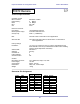
Technical Specifications
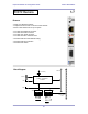
Controller module
Micro controller: MCF8250 “Coldfire”
Flash memory: 8 MByte
RAM: 16 MByte
RTC: DS 1306
OS: eCos
External connectors
LAN (RJ45): 10/100 Mbit/sec Ethernet
RS232 (Sub-D / 9pin): Controller serial interface 1
CAN (RJ 45): CAN 1.1 (125kBit/sec)
INIT: The INIT button is reserved for future applications
STATUS LED: The status LED lights yellow for the moment. It is reserved for
future applications
Factory settings
IP address: 10.110.xxx.yyy where xxx and yyy is factory calculated from the
MAC address of the unit (to avoid address conflicts when installing
systems with multiple frame controllers)
Subnet mask: 255.255.0.0
Gateway: No entry
Controller ID: 0
Frame address: 0
CAN termination: Off
General
Back plane connector: ref. to DIN41612, 64pin, a+b, male
Power supply: +5V DC
Consumption: approx. 300 mA
Dimensions: 3RU, 4HP, 175mm depth
Weight: ~200g
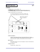
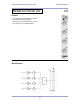
Connector Pin Assignment
RJ45 LAN
Pin # Function
1 Tx +
2 Tx -
3 Rx +
4
5
6 Rx -
7
8
Sub-D RS232
Pin # Function
1 DCD
2 TxD
3 RxD
4 DTR
5 GND
6 DSR
7 CTS
8 RTS
9 N.C.
RJ45 CAN
Pin # Function
1 CAN-H
2 CAN-L
3
4 GND
5 GND
6
7
8
FC972 Remote