
Instruction manual


System 5 Digital Audio Mixing System Operation Manual Channels and Strips
110
8.4 Channel Processing Functions
System 5 provides flexible and complete programmable functions for each channel:
Input, Dynamics, EQ, Filters, Aux Sends, and Panning.
8.4.1 Inputs
Each channel has an A and B input. See Section 8.3.1 on page 108 to learn about assigning
sources for these inputs. The Inpt knob (bottom) can feed A, B, or A+B to the channel.
These two inputs can be used in many ways but a common application is one Mic and
one Line. Another common use is for monitor inputs: Channel 1A is from the Group 1
Bus output while 1B is from the recorder’s track 1 output. The A/B source switch then
acts as a bus/tape switch.
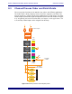
Press the Input function key to display the input controls on the knobset (Figure 8-10).
Press the X key to display the B input page with the same controls as the A input. Press
the X key again to display the Signal Processing In/Out page.
Atrm and Aphs have corresponding controls for the B input; Dly and Inp adjust one
parameter that applies to both inputs.
Figure 8-10 Input A (left) and Signal Processing In/Out (right) knobsets
g
HiZ
4
8V
HPF
Ga
i
n
A
t
rm
A
p
hs
Dl
y
I
n
p
Analog Controls
Page keys display
Input B and Signal Processing
In/Out pages
Digital Controls
Dl
y
D
yn
Fad
M
t
r
E
Q
F
il
t
I
n
s