
User`s guide
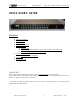


Preliminary Manual RELAY BOX - RB132/GP132 USER’S GUIDE
EUPHONIX INC - RB132/GP132 p3 Wednesday, August 26
th
, 2000
Installation
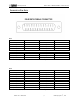
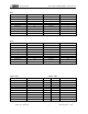
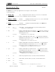
25-pin Dsub connector RT1 – RT4
Each connector has 8 relay outputs and 8 tally inputs. Both outputs and inputs share common lines,
so special care is required when multiple devices are connected to the same connector.
Tally inputs will accept from 5 volts to 24 volts, both DC and AC. Please contact Euphonix Customer
Service if you are planing to apply over 24 volts.
The relays used in this unit are rated at 500mA maximum. An additional driver circuit is required to
drain more current beyond this rating.
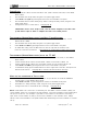
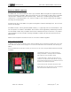
Connecting to a CS2000 / CS3000 series Mixing Console
The GP132 is connected to a CS2000/CS3000 with a MIDI cable. Currently, there are two ports
available for the GP132. Which port you will be using depends on what job you want the GP132 to do.
Method One is to connect to the DSC MIDI port which is located under the Mix Controller. This
allows 16GPI triggers known as fader starts and Track Arming for the Multi-Track Recorder or
dubber, etc.
Method Two is to connect the GP132 MIDI in/out to port#3 on the MIDI EXPRESS interface unit.
In this way, GP132 can control the desk or be controlled from the desk by using Note On/Off
messages and/or Continuous Controller (C.C) messages. When Continuous Control is used, the
console parameters such as fader level, pan, aux levels will work between fully minimum or fully
maximum, since the GP132 sends/receives MIDI value zero or 127. Special caution must to be
taken when using C.C.mode because of this.
The description of how to configure the desk is described in the CS3000 Operation Manual Version
3.0 page-12 – 7 to 12-9 for external control. Fader starts are described in the MixView Software
Supplement Version 3.0 Revision 2 page 10 – 70. they are also described in the
Euphonix MX464 Operation & Service Manual 1 – 16 and 1-17, since the GP132 is working in MX464
simulation mode, in this case.
This manual contains these related sections from the above referenced manuals in the APPENDIX
section.