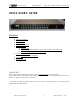
Preliminary Manual 840-08596-01 RELAY BOX - RB132/GP132 USER’S GUIDE GP132 USER’S GUIDE CONTENTS q q q q q q q q PACKAGE CONTENTS INTRODUCTION INSTALLATION CONNECTOR PIN OUTS SETUP THE UNIT q FADER START q TRACK ARMING (RECORD READY SELECT) FOR THE MULTI TRACK MACHINE q MUTE ON/ OFF CONTROLLED BY TALLY SIGNAL THEORY OF OPERATION q HOW TO REPLACE THE EPROM APPENDIX -1 SPECIFICATIONS IMPORTANT Before installing this equipment, please read the INSTALLATION section on page 3.
Preliminary Manual RELAY BOX - RB132/GP132 USER’S GUIDE PACKAGE This package contains : 1. One GP132. 2. One 8 foot Power cable. 3. One User’s guide. Introduction The GP132 is a multiple purpose relay box which can perform several functions. 1. It can provide the CS2000/3000 system with a Track Arming unit, for professional Tape Machines such as MTR90, A820, A827, PCM3324, PCM3348, and many others. 2.
Preliminary Manual RELAY BOX - RB132/GP132 USER’S GUIDE Installation 25-pin Dsub connector RT1 – RT4 Each connector has 8 relay outputs and 8 tally inputs. Both outputs and inputs share common lines, so special care is required when multiple devices are connected to the same connector. Tally inputs will accept from 5 volts to 24 volts, both DC and AC. Please contact Euphonix Customer Service if you are planing to apply over 24 volts. The relays used in this unit are rated at 500mA maximum.
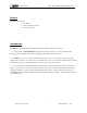
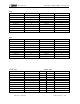
RELAY BOX - RB132/GP132 USER’S GUIDE Preliminary Manual CONNECTOR PIN OUTS RT1 RELAY OUTPUT Relay-1 Relay-2 PIN NUMBER 2 16 TALLY INPUT Tally-1 Tally-2 PIN NUMBER 1 15 Relay-3 Relay-4 Relay-5 Relay-6 Relay-7 5 19 8 22 11 Tally-3 Tally-4 Tally-5 Tally-6 Tally-7 4 18 7 21 10 Relay-8 25 Tally-8 Relay out common 13 Tally in common NOTE: Pin 3,6,9,12,14,17,20 and 23 are connected internally.
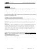
RELAY BOX - RB132/GP132 USER’S GUIDE Preliminary Manual RT3 RELAY OUTPUT Relay-17 Relay-18 Relay-19 PIN NUMBER 2 16 5 TALLY INPUT Tally-17 Tally-18 Tally-19 PIN NUMBER 1 15 4 Relay-20 Relay-21 Relay-22 Relay-23 19 8 22 11 Tally-20 Tally-21 Tally-22 Tally-23 18 7 21 10 Relay-24 25 Tally-24 Relay out common 13 Tally in common NOTE: Pin 3,6,9,12,14,17,20 and 23 are connected internally.
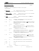
RELAY BOX - RB132/GP132 USER’S GUIDE Preliminary Manual SETTING UP THE UNIT VER 0.4H FIRMWARE The GP132 has a three way toggle switch on the right of the front panel. It has three states : q Relays only q Relays + Tallies q Setup 1. MIDI (UP) Displays the state of the RELAY CLOSURES (OUTPUTS) and allows control of the RELAY CLOSURES (OUTPUTS) manually from the front panel.
RELAY BOX - RB132/GP132 USER’S GUIDE Preliminary Manual 10. . PRESS DOUBLE PRESS 11. . PRESS DOUBLE PRESS 12. . PRESS DOUBLE PRESS 13. . 14. . 15. . no function. Display & Set TALLY OPTO' (INPUT ) Map for MIDI NOTE ON / O FF. (INPUT ) Map for MIDI CONTINUOUS CONTROLLERS . (INPUT ) Map for MIDI SYSTEM E XCLUSIVE. no function. Display & Set TALLY OPTO' no function. Display & Set TALLY OPTO' PRESS no function. PRESS no function. PRESS no function.
Preliminary Manual RELAY BOX - RB132/GP132 USER’S GUIDE FADER START 1. 2. 3. 4. 5. Connect a MIDI cable from the DSC MIDI OUT (under the Mix Controller) to the GP132 MIDI INPUT. Put the GP132 into Setup mode, using the front panel toggle switch. Select MIDI and SysEx by pressing buttons 1 and 5 on the GP132 front panel. Put the GP132 back to either “Relay Only” mode or “Relay and Tally” mode, using the front panel toggle switch. Configure the DSC for fader starts. > See page 13-18.
Preliminary Manual RELAY BOX - RB132/GP132 USER’S GUIDE NOTES ON GP132 OPERATION The GP132 has a bi-directional MIDI control port, however, MMC and SysEx are single directional and are received by the GP132. When you use this unit for track arming or fader starts, the GP132 receives MIDI commands and then activates relays. Therefore, if something wrong with MIDI connection or if the GP132 power is off, there is no way for the console to know that the GP132 is not being controlled properly.
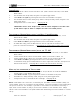
Preliminary Manual RELAY BOX - RB132/GP132 USER’S GUIDE APPENDIX-1: Reference section of the Console manual Operation Manual Version 3.0 Revision CS3000 SECTION 12 : MIDI REMOTE CONTROL................... 12 – 7 to 12-9 Remote Control of External Equipment (OUT) You can continuously control external MIDI equipment using group master faders & mutes via port 3 of the console’s MIDI interface box. (Refer to your equipment operation manuals for information on making connections.
Preliminary Manual RELAY BOX - RB132/GP132 USER’S GUIDE MIDI Chan: Designates MIDI Chan: Designates what MIDI channel is to be used for the communication between the console and the external device. (Na/Nc) Control Num: Designates the control number which the selected console object will send out (or respond to). (Na/Nc) MIDI Mode: In the case of the MIDI Out screen, designates whether the console is currently sending MIDI data (OUT) or not active (OFF).
Preliminary Manual RELAY BOX - RB132/GP132 USER’S GUIDE In this case, the Lower Group Master has been duplicated three times. Notice that the MIDI Mode field defaults to active (OUT). These copies can then be independently configured. To delete any selected duplicates, press [Del]. Remote Control of Console Objects by External Equipment (IN) You can also continuously control console objects using external MIDI equipment via port 3 of the console’s MIDI interface box.
RELAY BOX - RB132/GP132 USER’S GUIDE Preliminary Manual MixView Software Supplement Version 3.0 Revision 2 SECTION 10 : MX464 Pulsed GPI Switching GPI control has been enhanced in v3.0 software through the addition of the pulsed GPI control parameters. Each GPI relay can be set for pulsed (momentary y) operation. Additionally , this behavior can be set to operate in either or both fader movement directions and for selectable timing intervals (pulse width) from 20mS - 2.54s.
Preliminary Manual RELAY BOX - RB132/GP132 USER’S GUIDE Column names and their functions are as follows: • RELAY: The relay number being addressed. • INIT: The state to which a relay is set when initialized or reset. • TRIGGER: The fader object controlling the relay . • STATE: The “active” position of the relay when triggered by the upward movement of the fader object. • COMMENT: The name of the relay assigned by either the console or the user.
Preliminary Manual RELAY BOX - RB132/GP132 USER’S GUIDE As with MIDI and Fader -Linking screens, the [Enter] key duplicates the currently selected GPI object allowing it to be controlled from multiple faders. Press [F2] to sequence through the available INIT and STATE parameter settings and observe the DSC screen: It is advisable to set the INIT field first and then set the STATE field as the for mer always resets the latter to a default when subsequently accessed again.
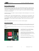
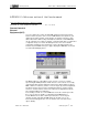
Preliminary Manual RELAY BOX - RB132/GP132 USER’S GUIDE Euphonix MX464 Operation & Service Manual GPI Relays With the GP132, any of a set of 16 relays can be actuated from a channel fader movement or “Fader start” .as it is sometimes called. The relays can be set to open or close when a fader is moved from the bottom of its travel. From the top level SmartDisplay menu, press [F3] (Auto) then [F3] (GPI). On the DSC Screen Display you will see the GPI assignment screen.
Preliminary Manual Configure GPI Relays RELAY BOX - RB132/GP132 USER’S GUIDE Follow the steps below to configure any relays between 1 and 16 : 1. From the GPI screen, use the SpinKnob to select the relay to configure. The designated relay is displayed above F1; 2. Using the [F2] and [F4] SmartDisplay function keys, set the Initial and On States of the designated relay; 3. Press the attention key of the fader that you want to control the relay.
Preliminary Manual RELAY BOX - RB132/GP132 USER’S GUIDE initialize upon Title load. If the light is off, the relays will stay in their current state after a Title load. The faders must be moved back down to their stops to initialize them. The default setting is Load on.
Preliminary Manual RELAY BOX - RB132/GP132 USER’S GUIDE SPECIFICATIONS OPERATING VOLTAGE : 100V-240VAC 50/60HZ AUTO RANGING POWER COMSUMPTION: 15 W MAX. DIMENSIONS: 19.0” (W ) X 1.73” (H) X 6.42” (D) 485mm (W ) X 44mm (H) X 163mm (D) WEIGHT: 3.5LBS (1.6KG ) Maximum Relay Current : 500mA Maximum Relay Voltage : 200V DC Maximum Relay Power : 10W (Total) Tally voltage range: Min: 5V Max:24V Specifications are subject to change without notice.