www.phoenix-mt.com PHÖNIX Messtechnik GmbH Magnetgesteuerte Grenzschalter Typ 740.0060 Typ 740.0065 Typ 740.0065NA BEDIENUNGSANLEITUNG Magnetically operated Level Switch Type 740.0060 Type 740.0065 Type 740.
Inhaltsverzeichnis 1 2 3 ALLGEMEINE BESCHREIBUNG 1.1 Typ 740.0060 3 1.2 Typ 740.0065/65N 3 MONTAGEHINWEISE 4 2.1 Lieferzustand 4 2.2 Umkehr der Wirkungsrichtung 4 INBETRIEBNAHME 5 3.1 Montage 5 3.2 Elektrischer Anschluss 5 3.2.1 Leistungsschalter 5 3.2.2 Kleinsignalschalter 6 3.2.3 Namur-Schalter 6 3.3 4 3 Grundeinstellung des Schaltzustandes 6 BEDIENUNG 6 4.1 Zweipunkt-Regelung mit 740.0060 6 4.2 Einsatz des Typs 740.
2.1 Delivery 10 2.2 Reversing the direction of switching 10 COMMISSIONING 3.1 Mounting 11 3.2 Electrical connections 11 3.2.1 Power switch 11 3.2.2 Miniswitch 11 3.2.3 Namur switch 12 3.3 4 11 Setting the switch position 12 OPERATING INSTRUCTIONS 12 4.1 Two-step action with overlap with one PHÖNIX type 740.0060 level switch 12 4.2 Using the type 740.0065NA in a hazardous area 13 4.
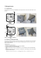
1 Allgemeine Beschreibung Die PHÖNIX Grenzschalter Typ 740.0060/65 werden zusammen mit magnetisch gesteuerten Flüssigkeitsstandanzeigern verwendet. Ihr Schaltverhalten ist bistabil. Bei Stromausfall und -wiederkehr ist der Schaltzustand durch magnetische Speicherung stets aktuell. Die Wirkungsrichtung des Schaltvorgangs ist durch Montage der Platine umkehrbar (Kap. 2.2). Der Grenzschalter besitzt eine Hysterese, die vom verwendeten Anzeiger abhängig ist (s. Kap. 9).
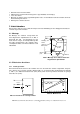
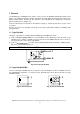
2 Montagehinweise 2.1 Lieferzustand Die PHÖNIX Grenzschalter Typ 740.0060/65 werden ausgeliefert wie in der nachstehenden Abb. 3a dargestellt: AUS EIN Abb. 3a: Lieferzustand EIN AUS Abb. 3b: nach Umkehr der Wirkrichtung 2.2 Umkehr der Wirkungsrichtung Eine Umkehr der Wirkungsrichtung entspricht der entgegengesetzten Schaltfunktion bei gleicher Magnetpolarität. Dabei ist darauf zu achten, dass die Kabelverschraubung immer nach unten zeigt, wie in den Abb. 3a und 3b dargestellt.
• • • • Anklemmen der Anschlussdrähte Anbringen der Sicherheitsabdeckung (nur bei Typ 740.0060, sehr wichtig !!) Lösen des Halters Montage des Halters an der gegenüberliegenden Seite. Um den Abstand aufrecht zu halten die zweite Reihe Bohrungen benutzen. • Anbringen des Gehäusedeckels 3 Inbetriebnahme Der Anschluss darf nur von geschultem Fachpersonal unter Einhaltung der einschlägigen Sicherheitsvorschriften vorgenommen werden 3.
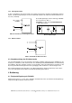
3.2.2 Kleinsignalschalter In dieser Schaltung ist der Grenzschalter ein normaler mechanischer Schalter (Reedkontakt) für kleine Gleich- oder Wechselspannungen. Für den Reedkontakt sind daher die üblichen Schutzmaßnahmen vorzusehen (s. Abb. 6b). Bei Schaltspannungen >24V ist beim Typ 740.0060 R1 zu entfernen (s. Abb. 1). Kleinlast Grenzwerte (s. Kap. 9) und Schutzmaßnahmen (s. Abb. 6b) beachten. Abb. 6b: Schutzmaßnahmen für Gleich- und Wechselspannungen Abb. 6a: Anschluss als Kleinsignalschalter 3.2.
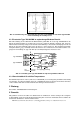
Abb. 8: Verwirklichung einer Zweipunkt-Regelung mit einem PHÖNIX Grenzschalter Typ 740.0060 unter Ausnutzung der Schalthysterese 4.2 Einsatz des Typs 740.0065NA im explosionsgefährdeten Bereich Durch Beschaltung des Reedkontakts mit Widerständen gemäß Abb. 2b ist der Typ 740.0065NA für den Einsatz in Namurschaltkreisen geeignet.
7 Entsorgung Der Kunde übernimmt die Pflicht, die gelieferte Ware nach Nutzungsbeendigung auf eigene Kosten nach den gesetzlichen Vorschriften ordnungsgemäß zu entsorgen. 8 Störungsbeistand Fehler keine Funktion kein bistabiles Verhalten kein Öffnen (740.
1 General The PHÖNIX type 740.0060/65 level switches can be used on all PHÖNIX magnetically-operated level gauges. The switching behaviour is bistable. Should the electrical supply fail and return, the position of the impulse magnet will be "memorised". The direction of the switching can be changed by reversing the printed circuit board (see chapter 2.2). The level switch hysteresis depends on the liquid level gauge (s. chapter 9) and can be used as a twostep action.
2 Mounting instructions 2.1 Delivery The PHÖNIX type 740.0060/65 level switch can be delivered in the configurations shown below: OFF ON Fig. 3a: as delivered ON OFF Fig. 3b: with inverted switching direction 2.2 Reversing the direction of switching A reversal of the direction of switching involves the opposite switching function. Please note that the cable-gland is always directed downwards, as shown in fig. 3a and 3b.
• Mount the bracket on the opposite side of the switch box. Use the second row of holes to keep the distance. • Remount the switch cover 3 Commissioning Authorised skilled personnel only recommended to connect the electrical circuits. 3.1 Mounting The mounting of the switch is done by two collars, which are supplied together with the switch, as shown in Fig. 4. The cable gland is directed downwards in any case. The switching point is situated nearby the middle of the box.
For switch type 740.0060 at voltages >24 V remove the resistor marked with R1 (s. fig. 1). low load Please observe limit values (chapter 8) and safety precautions (s. fig. 6b). Fig. 6b: safety precautions for operation in low DC/AC circuits. Fig. 6a: Connected as a mini switch 3.2.3 Namur switch 740.0065NA Fig. 7: Connecting of the Namur switch 3.3 Setting the switch position Before starting-up, the bistable Reed contact must be properly set, in relation to the float in the level gauge.
Fig. 8: A two-step action with a PHÖNIX level switch type 740.0060 utilising its hysteresis. 4.2 Using the type 740.0065NA in a hazardous area The limit switch type 740.0065NA is designed for usage in NAMUR-circuits (s. fig. 2b). It consists only of passive devices (switch and resistors), which allows - according to EN 50020 / VDE 0170 part 7 - the usage in hazardous areas zone 1 and 2, if they are part of a intrinsic save circuit and the maximum values of voltage, current and power are not exceeded.
7 Disposal The customer/enduser is obliged to take care for the disposal within the legal regulations. 8 Trouble shooting Failure no function no bistable behaviour the switch is always closed (740.
PHÖNiX www.phoenix-mt.com PHÖNIX Messtechnik GmbH PHÖNIX Messtechnik GmbH Salzschlirfer Straße 13 D-60386 Frankfurt Tel. +49/69/41 67 42 - 20 Fax +49/69/41 67 42 - 29 Internet: http://www.phoenix-mt.com e-mail: sales@phoenix-mt.