
User Manual


Operating Instructions Safety Switches CES-AR-C.2-CH
8
Mounting
Caution!
Safety switch e s must not be bypassed (br i d g i n g of co n t a c t s ) , turned away,
removed or otherwise rendered ineffective.
Ì On this topic pay attention in particular to the measures for reducing the pos-
sibility of bypassing according to EN 1088:1995.A2:2008, sec. 5.7.
Caution!
Risk of damage to equipment as a result of incorrect installation. Safety switches
must not be used as a mechanical end stop.
Ì Fit an additional end stop for the movable part of the safety guard.
Important!
Ì From the assured switch-off distance S
ar
, the safety outputs are safely shut
down.
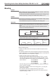
Ì When mounting several safety switches, observe the stipulated minimum
distance to avoid mutual interference.
min. 120 mm
Ì The operating distance changes during the mounting of the actuator as a
function of the material used for the safety guard.
Note the following points:
Ì Actuator and safety switch must be easily accessible for inspection and re-
placement.
Ì The switching operation must only be triggered by the specific actuator desig-
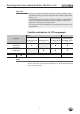
nated for this purpose. For permissible combinations please see the Table Pos-
sible combinations for CES components on page 4.
Ì Actuator and safety switch must be fitted so that
Ì the front faces are at the minimum switch-on distance 0.8 x S
ao
or closer
when the safety guard is closed (see section Operating distances). A mini-
mum distance dependent on the actuator must be maintained for a side ap-
proach direction: - For CES-A-BLN-R2 6 mm
- For CES-A-BLN-L2 6 mm
- For CES-A-BLN-U2 6 mm
- For CES-A-BDN-06 8 mm
Ì when the safety guard is open up to the distance S
ar
(assured switch-off dis-
tance), a hazard is excluded.
Ì the actuator is positively mounted on the safety guard, e.g. by using the
safety screws included.
Ì they cannot be removed or tampered with using simple means.
Ì Pay attention to the maximum tightening torque for the safety switch and
actuator mountings of 1 Nm.