
User Manual

Operating Instructions Safety Switches CES-AR-C.2-CH
15
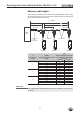
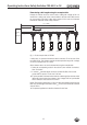
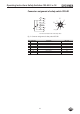
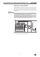
Connection of a single CES-AR-C
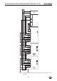
If a single CES-AR-C is used, connect the switch as shown in Figure 3. The OUT
output can also be connected here to a control system as a monitoring output.
The switch can be reset via the RST input. To do this, a voltage of 24 V is applied
to the RST input for at least 3 seconds. The RST input must be connected to 0 V
if it is not used.
Important!
The subsystem CES-AR complies with PL e in accordance with EN 13849-1. To
integrate the subsystem in a category 3 or 4 structure, it is necessary to monitor
the downstream load (the feedback loop must be monitored).
These examples show only an excerpt that is relevant for connection of the CES
system. The example illustrated here does not show complete system planning.
The user is responsible for safe integration in the overall system.
GND
DC 24 V
CES-AR-C #1
IB1
UB2
OA3
OB4
Plug connector (8-pin)
OUT5
IA6
0V7
RST8
WH
BN
GN
YE
GY
PK
BU
RD
-K1
-K2
-M1
M
A1
A2
A1
A2
13
14
13
14
Fig. 3: Connection example for a single CES-AR-C