Operating Instructions Non-Contact Safety Switch CES-AR-CR2-CH (Multicode) CES-AR-CL2-CH (Multicode) More than safety.
Operating Instructions Safety Switches CES-AR-C.
Operating Instructions Safety Switches CES-AR-C.2-CH Correct use The Coded Electronic Safety switches series CES are safety devices for monitoring movable safety guards. In combination with a separating safety guard and the machine control, this safety component prevents dangerous machine movements from occurring while the safety guard is open. A stop command is triggered if the safety guard is opened during the dangerous machine function.
Operating Instructions Safety Switches CES-AR-C.2-CH Important! ÌÌIn the case of series connection of more than 11 devices, the PFHd can be calculated according to one of the stated methods in EN ISO 13849-1:2008, Section 4.5.1. ÌÌIf the simplified method according to Section 6.3 of EN ISO 13849:2008-12 is used for validation, the Performance Level (PL) might be reduced when more than 11 devices are connected in series.
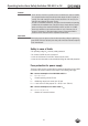
Operating Instructions Safety Switches CES-AR-C.2-CH Exclusion of liability and warranty In case of failure to comply with the conditions for correct use stated above, or if the safety instructions are not followed, or if any servicing is not performed as required, liability will be excluded and the warranty void. General safety instructions As the unique actuator codes are not evaluated, the CES-AR-C.
Operating Instructions Safety Switches CES-AR-C.
Operating Instructions Safety Switches CES-AR-C.2-CH If the safety door with the actuator should settle over time, the actuator can drift out of the read head operating distance. The device recognizes this and indicates that the actuator is in the boundary area (function available for V 1.1.2 and higher). This allows the safety door to be readjusted in time.
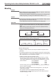
Operating Instructions Safety Switches CES-AR-C.2-CH Mounting Caution! Safety switches must not be bypassed (bridging of contacts), turned away, removed or otherwise rendered ineffective. ÌÌOn this topic pay attention in particular to the measures for reducing the possibility of bypassing according to EN 1088:1995.A2:2008, sec. 5.7. Caution! Risk of damage to equipment as a result of incorrect installation. Safety switches must not be used as a mechanical end stop.
Operating Instructions Safety Switches CES-AR-C.2-CH Electrical connection The following connection options are available: ÌÌSeparate operation ÌÌSeries connection with Y-distributors from EUCHNER (only with M12 plug connector) ÌÌSeries connection, e. g. with wiring in the control cabinet ÌÌOperation on an AR evaluation unit. Warning! In case of an error, loss of the safety function through incorrect connection. ÌÌTo ensure safety, both safety outputs (OA and OB) must always be evaluated.
Operating Instructions Safety Switches CES-AR-C.2-CH Caution! ÌÌPower devices which are a powerful source of interference must be installed in a separate location away from the input and output circuits for signal processing. The cable routing for safety circuits should be as far away as possible from the cables of the power circuits.
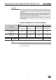
Operating Instructions Safety Switches CES-AR-C.2-CH Caution! Requirements for connection cables Risk of damage to equipment or malfunctions as a result of incorrect connection cables. ÌÌUse connection components and connection cables from EUCHNER ÌÌOn the usage of other connection components, the requirements in the following table apply. EUCHNER provides no warranty for safe function in case of failure to comply with these requirements.
Operating Instructions Safety Switches CES-AR-C.2-CH Maximum cable lengths Switch chains are permitted up to a maximum overall cable length of 200 m taking into account the voltage drop as a result of the cable resistance (see table below with example data and case example). lmax =200 m l2 l1 ln un = 24 V -20% umin = 24 V -10% iout 5 x 0,34 mm2 5 x 0,34 mm2 STATE DIA 5 x 0,34 mm2 oder 5 x 0,14 mm2 STATE DIA CES-AR # n CES-AR # n-1 n Iout (mA) Max.
Operating Instructions Safety Switches CES-AR-C.2-CH Determining cable lengths using the example table Example: 6 switches are to be used in series. Cabling with a length of 40 m is routed from a safety relay in the control cabinet to the last switch (#6) (conductor cross-section 0.34 mm²). Cables with a length of 20 m each are connected between the individual CES-AR safety switches. lmax = 140 m l2 = 5 x 20 m l1 = 40 m ln = 20 m un = min. 19,2 V Sicherheitsrelais iout = min.
Operating Instructions Safety Switches CES-AR-C.2-CH Connector assignment of safety switch CES-AR RST UB 0V IA IB OA OB OUT 8 2 7 6 7 8 6 1 5 4 1 3 4 5 Coding lug 2 3 View on the connection side of the safety switch Fig.
Operating Instructions Safety Switches CES-AR-C.2-CH Connection of a single CES-AR-C If a single CES-AR-C is used, connect the switch as shown in Figure 3. The OUT output can also be connected here to a control system as a monitoring output. The switch can be reset via the RST input. To do this, a voltage of 24 V is applied to the RST input for at least 3 seconds. The RST input must be connected to 0 V if it is not used. Important! The subsystem CES-AR complies with PL e in accordance with EN 13849-1.
Operating Instructions Safety Switches CES-AR-C.2-CH Warning! In case of an error, loss of the safety function through incorrect connection. ÌÌTo ensure safety, both safety outputs (OA and OB) must always be evaluated. Single-channel use of the safety outputs leads to a loss of the category in accordance with EN ISO 13849-1. RST IA PK 6 RD 8 OUT GY 5 0V OB YE 4 BU 7 UB OA BN 2 GN 3 WH 1 IB DC 24 V A1 -K1 13 A2 14 -K2 A1 13 A2 14 Plug connector (8-pin) CES-AR-C #1 -M1 GND Fig.
Operating Instructions Safety Switches CES-AR-C.2-CH Connection of several CES-AR-C in a switch chain Important! ÌÌAn AR switch chain may contain a maximum of 20 safety switches. ÌÌIn the estimation of the PL for the overall system, a maximum value of 100 years can be assumed for the MTTFd according to the limit value in EN ISO 13849-1:2008, section 4.5.2. This corresponds to a minimum value for the PFHd of 2.47x10⁻⁸/h.
Terminating plug 18 IB 6 IA Safety Inputs 1 8 Y-distributor 5 RST 2 UB 7 0V OA 4 OB CES Safety Outputs OUT 3 5 OUT 3 OA IB 6 IA Safety Inputs 1 8 RST 2 UB 7 0V Y-distributor OB CES Safety Outputs 4 IB 1 6 8 2 7 5 3 4 IA 4 4 OB 4 IB 0V 2 2 OA 3 3 0V 2 UB 1 IA RST 5 1 5 UB Read Head 1 Read Head RST Y-distributor IB IA RST UB 0V OUT OA OB UB Terminating plug IB 6 IA Safety Inputs 1 8 RST 2 UB 7 0V Y-distributor 5 3 OA 4 O
Operating Instructions Safety Switches CES-AR-C.2-CH Notes for operation with safe control systems Important! Devices with start button and feedback loop are not suitable for connection to safe control systems. Please observe the following requirements for connection to safe control systems: ÌÌUse a common power supply for the control system and the connected safety switches. ÌÌA clocked power supply must not be used for UB. Tap the supply voltage directly from the power supply unit.
Terminating plug 20 IB 6 IA 8 Safety Inputs 1 RST 2 UB 7 0V Y-distributor 3 OA 4 OB Safety Output OUT CES 5 IB 6 IA 8 RST Safety Inputs 1 2 UB 7 0V Y-distributor 5 3 OA 4 OB CES Safety Output OUT 1 IA RST 6 8 2 Safety Inputs IB UB 7 0V Y-distributor 5 OA OB LED1 UCM J 0V(UCM) CET 3 4 X2:3 X2:4 X2:5 X2:1 Safety Output OUT -X1 ET200 4 F-DO DO..M DO..
Operating Instructions Safety Switches CES-AR-C.2-CH Setup LED indicators LED STATE DIA Color State Significance illuminated Normal operation flashing - Teach-in operation or Power Up - Actuator in boundary area (V. 1.1.2 or higher (further signal functions: see status table) illuminated - Internal electronics fault - Fault at the inputs/outputs green red Initial setup 1. Apply operating voltage to the safety switch. ¨¨ The green LED flashes quickly (approx. 10 Hz).
Operating Instructions Safety Switches CES-AR-C.2-CH System status table Monitoring output OUT X off off closed on on closed On on flashes quickly 2 Hz Normal operation, door closed, actuator in the boundary area Re-adjust door (V. 1.1.2 or higher) closed off on 1x inverse Normal operation, door closed, preceding device in the switch chain signals "door open" (only with series connection) open off off 1x Normal operation, door open X off off 2x Input fault (e. g.
Operating Instructions Safety Switches CES-AR-C.2-CH Technical data Note! If a product data sheet is included with the product, the information on the data sheet applies in case of discrepancies with the operating instructions. Technical data for safety switch CES-AR-CR2-CH/CES-AR-CL2-CH Parameter Value min. typ. Unit max. Housing material PBT V0 GF30 Dimensions 95 x 30 x 12 mm 0.
Operating Instructions Safety Switches CES-AR-C.2-CH Typical system times The specified times are maximum values for AR switch chains with 20 devices. Individual devices have shorter system times. Ready delay: After switching on, the unit carries out a self-test for 8 s. The system is ready for operation only after this time. Switch-on time of safety outputs: The max.
Operating Instructions Safety Switches CES-AR-C.2-CH Dimension drawings and connector assignments Safety switch CES-AR-CR2-CH... Active face Fastening lug with reinforcement plate 3 6 12 23 4,25 With connection cable Connection cable with M12 plug connector 95 85 +0,5 M8x1 5,5 30 11 19,5 STATE DIA Length of cable piece: 1,000 mm or 2,000 mm 4,4 LEDs Active face 75,5 Safety switch CES-AR-CL2-CH...
Operating Instructions Safety Switches CES-AR-C.2-CH Connector assignment Safety switch CES-AR (8-pin plug) and Y-distributor (8-pin, socket) Pin Bridging plug 097645 4-pin , plug Function 1 IB 2 UB 3 OA 4 OB 5 OUT 6 IA 7 0V 8 RST Y-distributor with connection cable 111696 or 112395 Y-distributor 097627 Socket 2 3 4 5 Socket 2 3 1 6 4 5 8 15,1 6 1 8 ( 45 °) M12x1 M12x1 41 15 M 12x1 45 15 max. 45 7 7 Length l Order No.
Operating Instructions Safety Switches CES-AR-C.2-CH Technical data for actuator CES-A-BLN-... Parameter Value min. Unit typ. Housing material max. Plastic PBT Dimensions - CES-A-BLN-R2/CES-A-BLN-L2 - CES-A-BLN-U2 95 x 30 x 12 55 x 30 x 12 mm Weight - CES-A-BLN-R2/CES-A-BLN-L2 - CES-A-BLN-U2 0.04 0.02 kg Ambient temperature - 40 - Degree of protection acc.
Operating Instructions Safety Switches CES-AR-C.2-CH Switching distances Operating distance for center offset m = 0 (only in combination with actuator CES-A-BLN-...) Parameter Value Unit min. typ. max. - 15 - Switch-on distance 10 - - Switching hysteresis 1) 1 2 - Assured switch-off distance sar - in x/z direction - in y direction - - 40 60 Assured switch-on distance sao 1) mm Typical operating distance (only in combination with actuator CES-A-BLN-...
Operating Instructions Safety Switches CES-AR-C.2-CH Technical data for actuator CES-A-BDN-06 Parameter Value min. Unit typ. Housing material max. Macromelt PA-based plastic Dimensions mm 26 x ∅ 6 Weight 0.005 Ambient temperature - 40 kg - Degree of protection acc. to EN IEC 60529 + 70 °C IP 67 / IP 69K 1) Installation position Active face opposite read head Power supply Inductive via read head 1) With flush installation Installation options Dimension drawing 6 Ø 30 * min.
Operating Instructions Safety Switches CES-AR-C.2-CH Ordering information and accessories Designation Version Order No.
Operating Instructions Safety Switches CES-AR-C.2-CH Inspection and service Warning! Loss of the safety function because of damage to the system. In case of damage, the related component must be replaced completely. Only accessories or spare parts that can be ordered from EUCHNER may be replaced.
Operating Instructions Safety Switches CES-AR-C.
Operating Instructions Safety Switches CES-AR-C.
Euchner GmbH + Co. KG Kohlhammerstraße 16 D-70771 Leinfelden-Echterdingen info@euchner.de www.euchner.de Edition: 109308-05-05/13 Title: Operating Instructions Safety Switches CES-AR-C.2-CH (translation of the original operating instructions) Copyright: © EUCHNER GmbH + Co. KG, 05/2013 Subject to technical modifications, no responsibility is accepted for the accuracy of this information. More than safety.