
Manual


Operating Instructions AR Evaluation Unit CES-AR-AES-12
6
Function
The AR evaluation unit is used to evaluate the individual safety switches in an AR
switch chain and to reliably interrupt a safety circuit.
The unit has two inputs for the connection of an AR switch chain. The safety contacts
are switched as a function of the input signals. Downstream parts of the safety
circuit can be monitored using a feedback loop.
The switching states of the connected safety switches can be signaled by means
of monitoring outputs.
If the actuator on one of the safety switches in the AR switch chain is moved out
of the operating distance or if guard locking is deactivated, the AR evaluation unit
opens its relay contacts and the corresponding monitoring output is switched off.
The system is designed so that failures will not result in the loss of the safety func-
tion. The occurrence of failures is detected by cyclic self-monitoring at the latest
at the next demand to close the safety contacts.
The system can be started either manually using a start button or automatically.
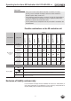
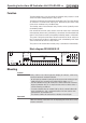
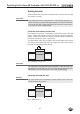
Block diagram CES-AR-AES-12
Fig. 1: Block diagram AR evaluation unit
Mounting
Caution!
Safety switche s must n o t be bypassed (bridging of contacts), tur n e d away,
removed or otherwise rendered ineffective.
Ì On this topic pay attention in particular to the measures for reducing the pos-
sibility of bypassing according to EN 1088:1995.A2:2008, sec. 5.7.
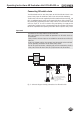
Ì The AR evaluation unit must be mounted in a control cabinet with a minimum
degree of protection of IP 54. A snap-in element on the rear of the device is
used for fastening to a DIN rail.
Ì If several evaluation units are mounted side by side in a control cabinet with-
out air circulation (e.g. fan), a minimum distance of 10 mm must be main-
tained between the evaluation units.
This distance enables the heat from the evaluation unit to dissipate.
Important!
Follow the mounting instructions in the accompanying documents for the safety
switches connected.
UB
X5:4
0V
X6:3
switch chain
Monitoring Outputs
Feedback
Loop
13 23
14 24
33 43
34 44
098225
DC 24 V
O1
X3:1
O2
X3:2
0V AR
X8:4
UB AR
X8:3
S
X5:3
DIA
X6:2
IB
X8:2
Y1
X5:1
Y2
X5:2
IA
X8:1
O3
X3:3
O4
X3:4
O5
X7:1
O6
X7:2
O7
X7:3
O8
X7:4
O9
X4:1
O10
X4:2
O11
X4:3
O12
X4:4
OUT AR
X6:1
UB
X6:4
CES- AR