
Manual


Operating Instructions AR Evaluation Unit CES-AR-AES-12
13
Connecting monitoring outputs on the AR evaluation
unit
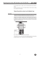
The AR evaluation unit has 14 short-circuit-proof semiconductor outputs that can
be used to signal different operating states, e.g. to a PLC. If the monitoring output
is active, a voltage of max. 24 V DC is present at the related terminal (referred to
the potential at terminal 0 V).
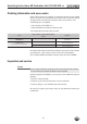
O3
O12
OUT
AR
DIA
O2
O1
min. 0,8x U
B
; max. 20 mA
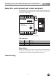
Fig. 8: Monitoring outputs CES-AR-AES
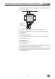
Significance of the signals with monitoring output active:
Ì O1 ... O12: Status of safety switches 1 ... 12
(actuator at operating distance or guard locking status)
Ì OUT AR: All connected safety switches in state Enable.
(All actuators in operating distance and all guard locking devices
active)
Ì DIA: Fault on the AR evaluation unit or on a safety switch in the AR
switch chain, or feedback loop was open during start (see section
Troubleshooting)
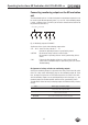
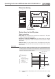
Assignment of safety switches to monitoring outputs
At least one monitoring output is assigned to each safety switch in the AR switch
chain. The safety switch with bridging plug has the monitoring output O1. From
here, the output assignments are incremented up to the last switch in the chain.
Several monitoring outputs are occupied depending on the switch type, e.g. one
monitoring output for the door position and one for the guard locking status.
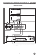
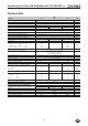
The table below shows how many monitoring outputs the individual safety switches
occupy.
Series Number (type) of monitoring outputs
CES-AR
1
(door position, OUT or diagnostics DIA)
CET1/2-AR
1
(status of guard locking OUT)
CET3/4-AR
2
(door position OUT D and status of guard locking OUT)