Operating Instructions AR Evaluation Unit CES-AR-AES-12 More than safety.
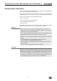
Operating Instructions AR Evaluation Unit CES-AR-AES-12 Contents Correct use Possible combinations on the AR evaluation unit 3 4 Exclusion of liability and warranty 4 General safety instructions 5 Function Block diagram CES-AR-AES-12 6 6 Mounting 6 Electrical connection Safety in case of faults Connecting AR switch chain Starting behavior Connecting safety contacts and feedback loop Connecting monitoring outputs on the AR evaluation unit Connection example 7 7 9 10 11 13 14 Setup 15 Status LED
Operating Instructions AR Evaluation Unit CES-AR-AES-12 Correct use The AR evaluation unit is used for the central evaluation of safety-related signals in AR switch chains. In combination with a separating safety guard and the machine control, this safety component prevents dangerous machine movements from occurring while the safety guard is open. A stop command is triggered if the safety guard is opened during the dangerous machine function or if guard locking is deactivated.
Operating Instructions AR Evaluation Unit CES-AR-AES-12 Important! ÌÌIn the case of series connection of more than 11 switches in a chain, the PFHd can be calculated according to one of the stated methods in EN ISO 13849-1:2008, Section 4.5.1. ÌÌIf the simplified method according to Section 6.3 of EN ISO 13849:2008-12 is used for validation, the Performance Level (PL) might be reduced when more than 11 devices are connected in series.
Operating Instructions AR Evaluation Unit CES-AR-AES-12 General safety instructions Safety switches fulfill personal protection functions. Incorrect installation or tampering can lead to severe injuries to personnel. The number of teach-in and switching operations is saved in the internal memory in the AR evaluation unit. If necessary, this memory can be read by the manufacturer.
Operating Instructions AR Evaluation Unit CES-AR-AES-12 Function The AR evaluation unit is used to evaluate the individual safety switches in an AR switch chain and to reliably interrupt a safety circuit. The unit has two inputs for the connection of an AR switch chain. The safety contacts are switched as a function of the input signals. Downstream parts of the safety circuit can be monitored using a feedback loop.
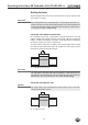
Operating Instructions AR Evaluation Unit CES-AR-AES-12 Electrical connection Warning! In case of an error, loss of the safety function through incorrect connection. ÌÌMonitoring outputs must not be used as safety outputs. ÌÌLay the connection cables with protection to prevent the risk of short circuits. Caution! Risk of damage to equipment or malfunctions as a result of incorrect connection.
Operating Instructions AR Evaluation Unit CES-AR-AES-12 Power supply The power supply of 24 V DC is supplied to the AR evaluation unit. The AR switch chain must be supplied with DC 24 V DC by the AR evaluation unit. +24 V 0V 0V +UB +UB connected together internally CES-AR-AES PE must be connected Fig.
Operating Instructions AR Evaluation Unit CES-AR-AES-12 Connecting AR switch chain The AR evaluation unit has two safety inputs to which the AR switch chain is connected. Safety inputs IA and IB have short circuit and earth fault monitoring. The AR switch chain must be supplied by the AR evaluation unit (terminals UBAR and 0VAR). An additional power supply may be required for these safety switches (e.g. for guard locking), depending on which safety switches are used in the AR switch chain (see Figure 5).
Operating Instructions AR Evaluation Unit CES-AR-AES-12 Starting behavior The AR evaluation unit can be placed in operation either using the autostart mode or by starting it manually. Important! If the configuration for the starting behavior is changed during operation (e.g. jumper removed), this change will be detected by the unit. The AR evaluation unit assumes the fault state as soon as the next request to close the safety contacts is received (see section Troubleshooting).
Operating Instructions AR Evaluation Unit CES-AR-AES-12 For the autostart mode, a jumper must be connected between the terminals S and Y1. By pulsing the output signal on Y1 the device detects short circuits on starting (e.g. static DC 24 V on input S). Connecting safety contacts and feedback loop Important! If you do not connect the feedback loop, the downstream devices will not be monitored. This situation will affect the safety category of your system.
Operating Instructions AR Evaluation Unit CES-AR-AES-12 If a feedback loop is not to be connected, a jumper must be fitted to the terminals Y1 and Y2 (see Figure 7). +24 V 13 23 33 43 CES-AR-AES 14 24 34 44 Y1 Y2 Subsequent devices (e.g. contactors) Fig.
Operating Instructions AR Evaluation Unit CES-AR-AES-12 Connecting monitoring outputs on the AR evaluation unit The AR evaluation unit has 14 short-circuit-proof semiconductor outputs that can be used to signal different operating states, e.g. to a PLC. If the monitoring output is active, a voltage of max. 24 V DC is present at the related terminal (referred to the potential at terminal 0 V). min. 0,8x UB ; max. 20 mA O1 O2 O3 O12 OUT AR DIA Fig.
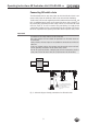
Operating Instructions AR Evaluation Unit CES-AR-AES-12 Connection example 24V 0V UB -U1 RST IA 8 IB 6 Read Head 2 1 Safety Output 7 5 CES 0V UB -U2 3 OUT RST OB IA 8 IB 6 Read Head 2 4 OA 1 Safety Output 7 5 CES 0V 3 OUT 4 OA OB - S18 13 14 -B1 CET UCM X2:4 J LED1 UB X2:5 X2:3 RST X1:2 IA X1:8 X1:6 Actuator Read Head 24 V DC Door Mon itoring Mon itoring Output RD X2:1 X1:7 0V(UCM) UB -K1 UB X6:4 X5:4 0V IA IB X8:1 X8:2 X2:2 X1:1 Safety O
Operating Instructions AR Evaluation Unit CES-AR-AES-12 Setup Warning! ÌÌPay attention to the notes on commissioning and on the teach-in process in the operating instructions for the safety switch used. ÌÌIn case of devices with teach-in input, ensure the circuit is correct. Proceed as follows: 1. Ensure nobody can be placed in danger during setup. 2.
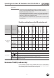
Operating Instructions AR Evaluation Unit CES-AR-AES-12 Status LEDs, control elements and terminal assignment The AR evaluation unit has status LEDs for the most important operating states. The significance of the individual LED states is explained in the System Status table in the section Troubleshooting.
Operating Instructions AR Evaluation Unit CES-AR-AES-12 System status table Door monitoring outputs Fault display OUT (yellow) open DIA (red) off off off Self-test after power up off off off Normal operation, at least one door open closed On On off Normal operation, all doors closed closed off On off Normal operation, all doors closed, start button not pressed or fault in the feedback loop closed off On On Normal operation, all doors closed, feedback loop was open during attempt t
Operating Instructions AR Evaluation Unit CES-AR-AES-12 Technical data Value Parameter min. typ. Housing material max. Unit Plastic PA6.6 Dimensions 114 x 99 x 22.5 Weight mm 0.25 kg Ambient temperature at UB = DC 24 V -20 - +55 °C Atmospheric humidity, not condensing - - 80 % Degree of protection according to EN 60529 IP20 Degree of contamination 2 Mounting DIN rail 35 mm according to EN 60715 Connection (plug-in screw terminals/coded) 0.
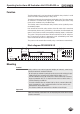
Operating Instructions AR Evaluation Unit CES-AR-AES-12 Dimension drawing 45 13 23 33 43 OUT AR 14 24 34 44 Y1 114 DIA 0V +UB Y2 S +UB EUCHNER Safety Unit DIA OUT STATE 99 CES-AR RESET O2 O3 O4 O5 O6 O7 O8 O9 O10 O11 O12 IA IB UB AR 0V AR O1 Suitable for DIN rail according to DIN 60715 System times for the AR system Typical system times Ready delay: After switching on, the unit carries out a self-test for 8 s. The system is ready for operation only after this time.
Operating Instructions AR Evaluation Unit CES-AR-AES-12 Ordering information and accessories Check whether all parts are complete. The connection terminals are not included with the unit. Cables for connection of the AR switch chain must also be ordered separately. Refer to the operating instructions of the safety switches used.
Operating Instructions AR Evaluation Unit CES-AR-AES-12 Service If service support is required, please contact: EUCHNER GmbH + Co. KG Kohlhammerstraße 16 D-70771 Leinfelden-Echterdingen Service telephone: +49 711 7597-500 E-mail: info@euchner.de Internet: www.euchner.
Operating Instructions AR Evaluation Unit CES-AR-AES-12 Declaration of conformity 22
Operating Instructions AR Evaluation Unit CES-AR-AES-12 23
Euchner GmbH + Co. KG Kohlhammerstraße 16 D-70771 Leinfelden-Echterdingen info@euchner.de www.euchner.de Edition: 098221-03-01/13 Title: Operating Instructions AR Evaluation Unit CES-AR-AES-12 (translation of the original operating instructions) Copyright: © EUCHNER GmbH + Co. KG, 01/2013 Subject to technical modifications, no responsibility is accepted for the accuracy of this information. More than safety.