Operating Instructions Non-Contact Safety Switch CES-AP-CR2-CH (Multicode) CES-AP-CL2-CH (Multicode) More than safety.
Operating Instructions Safety Switch CES-AP-C.
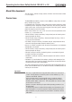
Operating Instructions Safety Switch CES-AP-C.2-CH About this document This document is valid for all safety switches CES-AP-C.2-CH with version number V 1.1.2 or higher. Correct use The Coded Electronic Safety switches of series CES are safety devices for monitoring movable safety guards. In combination with a separating safety guard and the machine control, this safety component prevents dangerous machine movements from occurring while the safety guard is open.
Operating Instructions Safety Switch CES-AP-C.
Operating Instructions Safety Switch CES-AP-C.2-CH General safety instructions Safety switches fulfill personal protection functions. Incorrect installation or tampering can lead to fatal injuries to personnel.
Operating Instructions Safety Switch CES-AP-C.
Operating Instructions Safety Switch CES-AP-C.2-CH If the safety door with the actuator should settle over time, the actuator can drift out of the read head operating distance. The device recognizes this and indicates that the actuator is in the boundary area (function available for V 1.1.2 and higher). This allows the safety door to be readjusted in time.
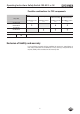
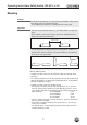
Operating Instructions Safety Switch CES-AP-C.2-CH Mounting Caution! Risk of damage to equipment as a result of incorrect installation. Safety switches must not be used as a mechanical end stop. ÌÌFit an additional end stop for the movable part of the safety guard. Important: ÌÌFrom the assured switch-off distance Sar, the safety outputs are safely shut down. ÌÌWhen mounting several safety switches, observe the stipulated minimum distance to avoid mutual interference. Installation options min.
Operating Instructions Safety Switch CES-AP-C.2-CH Electrical connection Warning! In case of an error, loss of the safety function through incorrect connection. ÌÌTo ensure safety, both safety outputs (OA and OB) must always be evaluated. ÌÌThe monitoring output OUT must not be used as a safety output. ÌÌLay the connection cables with protection to prevent the risk of short circuits. Caution! Risk of damage to equipment or malfunctions as a result of incorrect connection.
Operating Instructions Safety Switch CES-AP-C.2-CH Important: If the device does not appear to function when operating voltage is applied (e.g. green STATE LED does not flash), the safety switch must be returned unopened to the manufacturer. Notes for operation with safe control systems Important: Devices with start button and feedback loop are not suitable for connection to safe control systems.
Operating Instructions Safety Switch CES-AP-C.2-CH Safety in case of faults ÌÌThe operating voltage UB is reverse polarity protected. ÌÌThe contacts OA/OB are short circuit proof. ÌÌA short circuit between OA and OB is detected by the switch. ÌÌA short circuit in the cable can be excluded by laying the cable with protection. Fuse protection for power supply The power supply must be provided with fuse protection depending on the current required for the outputs. The following rules apply: Max.
Operating Instructions Safety Switch CES-AP-C.2-CH Connector assignment and wire color for safety switch CES-AP-C.2-CH Plug connector with latching connection, 6-pin +UB 0V 4 S1.3 OA 3 5 S1.2 OB OUT NC S1.1 S1.4 1 S1.5 6 S1.6 2 Coding lug View on the connection side of the safety switch Fig.
Operating Instructions Safety Switch CES-AP-C.2-CH Connection Connect the device as shown in Figure 3. The OUT output can be connected to a control system as a monitoring output. Important: The subsystem CES-AP complies with PL e in accordance with EN 13849-1. To integrate the subsystem in a category 3 or 4 structure, it is necessary to monitor the downstream load (the feedback loop must be monitored). These examples show only an excerpt that is relevant for connection of the CES system.
Operating Instructions Safety Switch CES-AP-C.2-CH Warning! In case of an error, loss of the safety function through incorrect connection. ÌÌTo ensure safety, both safety outputs (OA and OB) must always be evaluated. Single-channel use of the safety outputs leads to a loss of the category in accordance with EN ISO 13849-1. NC 5 OUT A1 -K1 13 A2 14 6 OB 0V 3 4 OA 2 1 UB DC 24 V -K2 M8 plug-connector (6-pin) A1 13 A2 14 M -M1 CES-AP-C.2-... -M2 M GND Fig.
Operating Instructions Safety Switch CES-AP-C.2-CH Setup LED indicators LED STATE DIA Color State Significance illuminated Normal operation: Door closed flashing - Door open - Actuator in boundary area (refer to the status table for further signal functions) illuminated - Internal electronics fault - Fault at the inputs/outputs green red Initial setup 1. Apply operating voltage to the safety switch. ¨¨ The green LED flashes quickly. A self-test is performed during this time.
Operating Instructions Safety Switch CES-AP-C.2-CH System status table Normal operation Fault display closed on closed on flashes quickly 2 Hz open off 1x Normal operation, door open closed off 3x Defective actuator (e.g. fault in code or code not readable) X off 4x Output error (e.g. short circuits, loss of switching ability) X off 5x Internal fault (e.g.
Operating Instructions Safety Switch CES-AP-C.2-CH Technical data Note: If a product data sheet is included with the product, the information on the data sheet applies in case of discrepancies with the operating instructions. Technical data for safety switch CES-AP-CR2-CH/ CES-AP-CL2-CH Parameter min.
Operating Instructions Safety Switch CES-AP-C.2-CH Typical system times Ready delay: After switching on, the unit carries out a self-test. The system is ready for operation only after this time. Switch-on time of safety outputs: The max. reaction time from the moment when the actuator is at the operating distance (safety door closed) to the moment when the safety outputs switch on Ton is 400 ms.
Operating Instructions Safety Switch CES-AP-C.2-CH Technical data for actuator CES-A-BLN-... Parameter Value min. Unit typ. Housing material max. Plastic PBT Dimensions - CES-A-BLN-R2/CES-A-BLN-L2 - CES-A-BLN-U2 95 x 30 x 12 55 x 30 x 12 mm Weight - CES-A-BLN-R2/CES-A-BLN-L2 - CES-A-BLN-U2 0.04 0.02 kg Ambient temperature - 40 - Degree of protection acc.
Operating Instructions Safety Switch CES-AP-C.2-CH Switching distances Operating distance for center offset m = 0 (only in combination with actuator CES-A-BLN-...) Parameter Value Unit min. typ. max. - 15 - Switch-on distance 10 - - Switching hysteresis 1) 1 2 - Assured switch-off distance sar - in x/z direction - in y direction - - 40 60 Assured switch-on distance sao 1) mm Typical operating distance (only in combination with actuator CES-A-BLN-...
Operating Instructions Safety Switch CES-AP-C.2-CH Technical data for actuator CES-A-BDN Parameter Value min. Unit typ. Housing material max. Macromelt PA-based plastic Dimensions Weight Ambient temperature 26 x ∅ 6 mm 0.005 kg - 40 - Degree of protection acc. to EN IEC 60529 + 70 °C IP67 / IP69K 1) Installation position Active face opposite read head Power supply Inductive via read head 1) With flush installation Dimension drawing Installation options 6 Ø 30 * min.
Operating Instructions Safety Switch CES-AP-C.2-CH Ordering information and accessories Designation Version Order No.
Operating Instructions Safety Switch CES-AP-C.2-CH Inspection and service Warning! Loss of the safety function because of damage to the system. In case of damage, the related component must be replaced completely. Only accessories or spare parts that can be ordered from EUCHNER may be replaced.
Operating Instructions Safety Switch CES-AP-C.
Operating Instructions Safety Switch CES-AP-C.
Euchner GmbH + Co. KG Kohlhammerstraße 16 D-70771 Leinfelden-Echterdingen info@euchner.de www.euchner.de Edition: 103913-07-01/13 Title: Operating Instructions Safety Switch CES-AP-C.2-CH (translation of the original operating instructions) Copyright: © EUCHNER GmbH + Co. KG, 01/2013 Subject to technical modifications; no responsibility is accepted for the accuracy of this information. More than safety.