Operating Instructions Non-Contact Safety Switch CES-AP-C01-AH (Unicode) More than safety.
Operating Instructions Safety Switch CES-AP-C01-AH Contents About this document 3 Correct use Possible combinations for CES components 3 4 Exclusion of liability and warranty 4 General safety instructions 5 Function 6 Changing the approach direction 7 Mounting 8 Electrical connection Notes on operation with safe control systems Devices for direct connection to IP65 field modules Safety in case of faults Fuse protection for power supply Requirements for connection cables Connector assignment, s
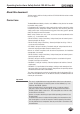
Operating Instructions Safety Switch CES-AP-C01-AH About this document This document is valid for all safety switches CES-AP-C01-AH with version number V 0.1.2 or higher. Correct use The Coded Electronic Safety switches series CES are safety devices for monitoring movable safety guards. In combination with a separating safety guard and the machine control, this safety component prevents dangerous machine movements from occurring while the safety guard is open.
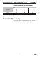
Operating Instructions Safety Switch CES-AP-C01-AH Possible combinations for CES components 100251 CES-A-BRN 098775 CES-A-BPA 071840 Safety switches CES-A-BBA Actuator CES-AP-C01 Key to symbols Combination possible Exclusion of liability and warranty In case of failure to comply with the conditions for correct use stated above, or if the safety instructions are not followed, or if any servicing is not performed as required, liability will be excluded and the warranty void.
Operating Instructions Safety Switch CES-AP-C01-AH General safety instructions Safety switches fulfill personal protection functions. Incorrect installation or tampering can lead to fatal injuries to personnel.
Operating Instructions Safety Switch CES-AP-C01-AH Function The device complies with the following safety requirements: ÌÌCategory 4, PLe according to EN ISO 13849-1 ÌÌRedundant design of the circuit in the unit with self-monitoring ÌÌThis means that the safety system still functions even if an internal component fails ÌÌThe switch state of the semiconductor outputs is continuously monitored internally ÌÌShort circuit detection at the safety outputs by pulse signals The following switch-on condition appl
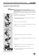
Operating Instructions Safety Switch CES-AP-C01-AH Changing the approach direction Caution! Risk of damage to equipment as a result of trapped cables. ÌÌMake sure that the cables are not trapped or torn off when the approach direction is changed. The active face of the read head can be adjusted in 5 directions. It is marked by the red face. The plug connector can be realigned in 45° steps to change the direction of the cable outlet (when using elbow connectors). 1.
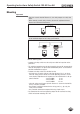
Operating Instructions Safety Switch CES-AP-C01-AH Mounting Important! ÌÌFrom the assured switch-off distance Sar, the safety outputs are safely shut down. ÌÌWhen mounting several safety switches, observe the stipulated minimum distance to avoid mutual interference. min. 80mm ÌÌIf the actuator is installed flush, the switching distance changes as a function of the installation depth and the safety guard material.
Operating Instructions Safety Switch CES-AP-C01-AH Electrical connection Warning! In the event of a fault: Loss of the safety function due to incorrect connection. ÌÌTo ensure safety, both safety outputs (OA and OB) must always be evaluated. ÌÌThe monitoring output DIA must not be used as a safety output. ÌÌLay the connection cables with protection to prevent the risk of short circuits. Caution! Risk of damage to equipment or malfunctions as a result of incorrect connection.
Operating Instructions Safety Switch CES-AP-C01-AH Important! If the device does not appear to function when operating voltage is applied (e.g. green STATE LED does not flash), the safety switch must be returned unopened to the manufacturer. Notes on operation with safe control systems Please observe the following requirements for connection to safe control systems: ÌÌUse a common power supply for the control system and the connected safety switches. ÌÌA clocked power supply must not be used for UB.
Operating Instructions Safety Switch CES-AP-C01-AH Safety in case of faults ÌÌThe operating voltage UB is reverse polarity protected. ÌÌThe contacts OA/OB are short circuit proof. ÌÌThe switch detects a short circuit between OA/OB and UB. ÌÌA short circuit between OA and OB is detected by the switch. ÌÌA short circuit in the cable can be excluded by laying the cable with protection.
Operating Instructions Safety Switch CES-AP-C01-AH Requirements for connection cables Caution! Risk of damage to equipment or malfunctions as a result of incorrect connection cables. ÌÌUse connection components and connection cables from EUCHNER ÌÌOn the usage of other connection components, the requirements in the following table apply. EUCHNER provides no warranty for safe function in case of failure to comply with these requirements. ÌÌPlease observe the maximum cable length of 200 m.
Operating Instructions Safety Switch CES-AP-C01-AH Connection Important! The subsystem CES-AP complies with PL e in accordance with EN 13849-1. To integrate the subsystem in a category 3 or 4 structure, it is necessary to monitor the downstream load (the feedback loop must be monitored). These examples show only an excerpt that is relevant for connection of the CES system. The example illustrated here does not show complete system planning. The user is responsible for safe integration in the overall system.
Operating Instructions Safety Switch CES-AP-C01-AH Warning! In the event of a fault: Loss of the safety function due to incorrect connection. ÌÌTo ensure safety, both safety outputs (OA and OB) must always be evaluated. Single-channel use of the safety outputs leads to a loss of the category in accordance with EN ISO 13849-1.
Operating Instructions Safety Switch CES-AP-C01-AH Setup LED indicators LED STATE DIA Color State Significance illuminated Normal operation flashing - Door open - Teach-in operation or Power Up - Actuator in limit range (refer to the status table for further signal functions) illuminated - Internal electronics fault - Fault at the inputs/outputs green red Teach-in function for actuator The actuator must be allocated to the safety switch using a teach-in function before the system forms a funct
Operating Instructions Safety Switch CES-AP-C01-AH Functional check After installation and any fault, the safety function must be fully checked. Proceed as follows: Warning! Danger of fatal injury as a result of faults in installation and functional check. ÌÌBefore carrying out the functional check, make sure that there are no persons in the danger area. ÌÌObserve the valid accident prevention regulations. 1. Switch on operating voltage. ÌÌThe safety switch carries out a self-test.
Operating Instructions Safety Switch CES-AP-C01-AH System status table Teach-in standby Setup Fault display closed on closed on flashes quickly 2 Hz open off 1x Normal operation, door open, no actuator taught open off 3x Door open, unit is ready for teach-in for another actuator (only short time after power-up) closed off 1 Hz X off closed off 3x Defective actuator (e.g. fault in code or code not readable) X off 4x Output error (e.g.
Operating Instructions Safety Switch CES-AP-C01-AH Technical data Note: If a product data sheet is included with the product, the information on the data sheet applies in case of discrepancies with the operating instructions. Technical data for safety switch CES-AP-C01-AH Parameter Value min. Housing material typ. Unit max. PBT V0 GF30 Dimensions According to EN 60947-5-2 Weight 0.
Operating Instructions Safety Switch CES-AP-C01-AH Typical system times Ready delay: After switching on, the unit carries out a self-test for 500 ms. The system is ready for operation only after this time. Switch-on time of safety outputs: The max. reaction time from the moment when the actuator is at the operating distance (safety door closed) to the moment when the safety outputs switch on Ton is 400 ms.
Operating Instructions Safety Switch CES-AP-C01-AH Technical data for actuator CES-A-BBA Parameter Value min. Housing material Unit typ. max. Fortron, reinforced thermoplastic, fully encapsulated Dimensions Weight Ambient temperature - 25 42 x 25 x 12 mm 0.02 kg - Degree of protection acc.
Operating Instructions Safety Switch CES-AP-C01-AH Switching distances Operating distance for center offset m = 0 (only in combination with CES-A-BBA actuator) Parameter Value Unit min. typ. max. - 18 - Switch-on distance 15 - - Switching hysteresis 1) 1 3 - Assured switch-off distance sar - - 45 Assured switch-on distance sao 1) mm 1) The values apply for surface installation of the actuator.
Operating Instructions Safety Switch CES-AP-C01-AH Technical data for actuator CES-A-BPA Parameter Value min. Unit typ. Housing material max. PBT Dimensions 40 x 40 x 10 mm 0.025 kg Weight Ambient temperature - 25 - Degree of protection acc.
Operating Instructions Safety Switch CES-AP-C01-AH Switching distances Operating distance for center offset m = 0 (only in conjunction with actuator CES-A-BPA on surface mounting) Parameter Value Unit min. typ. max. - 22 1) - Switch-on distance Assured switch-on distance sao 18 - - Switching hysteresis 1 2 - Assured switch-off distance sar - - 58 mm 1) On surface mounting on aluminum; in a non-metallic environment the typical switching distance increases to 30 mm.
Operating Instructions Safety Switch CES-AP-C01-AH Technical data for actuator CES-A-BRN Parameter Value min. Housing material Unit typ. max. PPS Dimensions Weight Ambient temperature - 25 Degree of protection acc. to EN IEC 60529 80 x 40 x 15 mm 0.
Operating Instructions Safety Switch CES-AP-C01-AH Switching distances Operating distance for center offset m = 0 (only in combination with actuator CES-A-BRN) Parameter Value Unit min. typ. max. - 27 - Switch-on distance 20 - - Switching hysteresis 1) - 3 - Assured switch-off distance sar - - 75 Assured switch-on distance sao 1) mm 1) The values apply for surface installation of the actuator on steel.
Operating Instructions Safety Switch CES-AP-C01-AH Ordering information and accessories Designation CES-AP-C01-AH-SB-111145 Connection cable, 5-pin, with flying lead Extension cable with M12 plug connector, 5-pin Version Order No.
Operating Instructions Safety Switch CES-AP-C01-AH Service If service support is required, please contact: EUCHNER GmbH + Co. KG Kohlhammerstraße 16 D-70771 Leinfelden-Echterdingen Service telephone: +49 711 7597-500 E-mail: info@euchner.de Internet: www.euchner.
Operating Instructions Safety Switch CES-AP-C01-AH Declaration of conformity 28
Operating Instructions Safety Switch CES-AP-C01-AH 29
Euchner GmbH + Co. KG Kohlhammerstraße 16 D-70771 Leinfelden-Echterdingen info@euchner.de www.euchner.de Edition: 112663-04-10/13 Title: Operating Instructions Safety Switch CES-AP-C01-AH (translation of the original operating instructions) Copyright: © EUCHNER GmbH + Co. KG, 10/2013 Subject to technical modifications; no responsibility is accepted for the accuracy of this information. More than safety.