Operating Instructions Non-Contact Safety Switch CES-AH-C03-AH-SM (Unicode) More than safety.
Operating Instructions Safety Switch CES-AH-C03-AH-SM Contents Correct use Possible combinations for CES components 3 4 Exclusion of liability and warranty 4 General safety instructions 5 System description 6 Montage 7 Electrical connection General notes Test pulses, pulsing and power control Behavior in case of faults Automatic restart and start button Safety in case of faults Fuse protection for power supply Voltage drop on cable and switch Connection cables and plug connectors Connector assignm
Operating Instructions Safety Switch CES-AH-C03-AH-SM Correct use The Coded Electronic Safety switches series CES are safety devices for monitoring movable safety guards. In combination with a safety guard, this safety component prevents dangerous machine movements from being performed for as long as the safety guard is opened. A stop command is triggered if the safety guard is opened during the dangerous machine function.
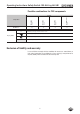
Operating Instructions Safety Switch CES-AH-C03-AH-SM Possible combinations for CES components CES-AH-C03-... 20 15 20 22 CES-A-BRN-100251 100 251 098 775 CES-A-BPA 088 786 071 840 CES-A-BBA Safety Switch CES-A-BCA Actuator 27 Combination possible, typ.
Operating Instructions Safety Switch CES-AH-C03-AH-SM General safety instructions Safety switches fulfill personal protection functions. Incorrect installation or tampering can lead to fatal injuries to personnel.
Operating Instructions Safety Switch CES-AH-C03-AH-SM System description The safety switch CES-AH-C03-AH-SM complies with the following safety requirements: ÌÌCategory 3 according to DIN EN ISO 13849-1 ÌÌProximity device with self-monitoring type PDF-S according to EN 60947-5-3.
Operating Instructions Safety Switch CES-AH-C03-AH-SM Montage Caution! Risk of damage to equipment as a result of incorrect installation. Safety switches must not be used as a mechanical end stop. ÌÌFit an additional end stop for the movable part of the safety guard. Important! ÌÌFrom the assured switch-off distance Sar, the safety outputs are safely shut down. ÌÌWhen mounting several safety switches, observe the stipulated minimum distance to avoid mutual interference. min.
Operating Instructions Safety Switch CES-AH-C03-AH-SM Electrical connection General notes Caution! Risk of damage to equipment or malfunctions as a result of incorrect connection. ÌÌTo avoid faults, the cable must be laid with protection. ÌÌThe power for the operating voltage and for the inputs +LA and +LB must be provided from a common power supply.
Operating Instructions Safety Switch CES-AH-C03-AH-SM Automatic restart and start button Pay attention to the notes for the following applications: Automatic start, with a jumper (+24 V are continuously present at the START input) ¨¨ The device restarts automatically after faults. Manual start (start via a start button) ¨¨ Prior to each restart the start button must be pressed ÌÌA sticking start button (fault due to welding etc.) is not detected by the device and results in an automatic restart.
Operating Instructions Safety Switch CES-AH-C03-AH-SM Voltage drop on cable and switch If a load is applied to the outputs, voltage drops will occur on the supply cables and on the switch. The voltage drops are to be taken into account during the calculation of the power available in the load connected. Parameter Value Unit Maximum resistance of an output path 250 mW Resistance for further connection cable (e.g.
Operating Instructions Safety Switch CES-AH-C03-AH-SM Connection cables and plug connectors Caution! Risk of damage to equipment or malfunctions as a result of incorrect connection cables. ÌÌUse EUCHNER connectors. ÌÌIf other connection components are used, the following recommendations apply. EUCHNER provides no warranty for safe function in case of failure to comply with these requirements. ÌÌThe maximum cable length should not exceed 50 m. Recommended connection cable: e.g.
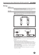
Operating Instructions Safety Switch CES-AH-C03-AH-SM Connection example Within the device, the shutdown of the two outputs LA and LB is dual-channel. As such, each of the outputs represents a separate safety output. UB START UB 7 +LB +LA 5 4 Internal logic START 2 LA 3 Feedback loop LB 6 2) 0V 8 NC 1 1) Feedback loop 2) 1) NC 9 GND 1) 2) Load, e.g. valve coil, DC motor, Ohmic load etc.
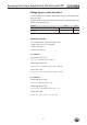
Operating Instructions Safety Switch CES-AH-C03-AH-SM Setup LED indicators LED STATE DIA Color green red State Significance illuminated Normal operation flashing Teach-in operation or Power Up (for further signal function see status table) illuminated - Internal electronics fault - Fault at the inputs/outputs Teach-in function for actuator The actuator must be allocated to the safety switch using a teach-in function before the system forms a functional unit.
Operating Instructions Safety Switch CES-AH-C03-AH-SM Functional check After installation and any fault, the safety function must be fully checked. Proceed as follows: Warning! Danger of fatal injury as a result of faults in installation and functional check. ÌÌBefore carrying out the functional check, make sure that there are no persons in the danger area. ÌÌObserve the valid accident prevention regulations. 1. Switch on operating voltage. ÌÌThe safety switch carries out a self-test.
Operating Instructions Safety Switch CES-AH-C03-AH-SM System status table Self-test X off closed on open off 1x Normal operation, door open open off 3x Door open, unit is ready for teach-in for another actuator (only short time after power-up) closed off 1 Hz X off X off 2x Overload (e.g. short circuit on a safety output) X off 3x Over-temperature X off 4x Output fault (e.g. fault on a switching element) X off 5x Internal fault (e.g.
Operating Instructions Safety Switch CES-AH-C03-AH-SM Technical data Note! If a product data sheet is included with the product, the information on the data sheet applies in case of discrepancies with the operating instructions. Technical data for safety switch CES-AH-C03-AH-SM Value Parameter min. typ. Housing material max. Unit Plastic Dimensions 40 x 40 x 171 Weight mm 0.
Operating Instructions Safety Switch CES-AH-C03-AH-SM Active face 5,3 40 M 23x1 30 40 LED status indication 5,3 7,3 23,3 40 90 171 17 45,5 40,3 40 0,3 27,5 15 34,5 0,5 Dimension drawing
Operating Instructions Safety Switch CES-AH-C03-AH-SM Typical system times Ready delay: After switching on, the unit carries out a self-test for 3 s. The system is ready for operation only after this time. Risk time according to EN 60947-5-3: If an actuator moves outside the operating distance, the safety outputs LA and LB on the corresponding safety switch are deactivated after a maximum of 260 ms. Difference time: The safety outputs LA and LB switch with a slight time offset.
Operating Instructions Safety Switch CES-AH-C03-AH-SM Technical data for actuator CES-A-BBA/CES-A-BCA Parameter Value min. Housing material - CES-A-BBA typ. Unit max. Fortron, reinforced thermoplastic, fully encapsulated - CES-A-BCA Plastic PE-HD without reinforcement, fully encapsulated Flat seal material (CES-A-BCA only) Fluororubber 75 FPM 4100 Dimensions 42 x 25 x 12 mm 0.02 kg Weight Ambient temperature - CES-A-BBA - 25 - + 70 - CES-A-BCA - 25 - + 50 Degree of protection acc.
Operating Instructions Safety Switch CES-AH-C03-AH-SM Switching distances Operating distance for center offset m = 0 (only in combination with actuator CES-A-BBA/CES-A-BCA) Parameter Value Unit min. typ. max. - 20 - Switch-on distance 18 - - Switching hysteresis 1) 2 3 - Assured switch-off distance sar - - 40 Assured switch-on distance sao 1) mm 1) The values apply for surface installation of the actuator.
Operating Instructions Safety Switch CES-AH-C03-AH-SM Technical data for actuator CES-A-BPA Parameter Value min. Unit typ. Housing material max. PBT Dimensions 40 x 40 x 10 mm 0.025 kg Weight Ambient temperature - 25 - Degree of protection acc.
Operating Instructions Safety Switch CES-AH-C03-AH-SM Switching distances Operating distance for center offset m = 0 (Only in conjunction with actuator CES-A-BPA on surface mounting) Parameter Value Unit min. typ. max. - 22 1) - Switch-on distance Assured switch-on distance sao 18 - - Switching hysteresis 1 2 - Assured switch-off distance sar - - 58 mm 1) On surface mounting on aluminum, in a non-metallic environment the typical switching distance increases to 30 mm.
Operating Instructions Safety Switch CES-AH-C03-AH-SM Technical data for actuator CES-A-BRN Parameter Value min. Housing material Unit typ. max. PPS Dimensions Weight Ambient temperature - 25 Degree of protection acc. to EN IEC 60529 80 x 40 x 15 mm 0.
Operating Instructions Safety Switch CES-AH-C03-AH-SM Switching distances Operating distance for center offset m = 0 (only in combination with actuator CES-A-BRN) Parameter Value Unit min. typ. max. - 27 - Switch-on distance 20 - - Switching hysteresis 1) - 3 - Assured switch-off distance sar - - 75 Assured switch-on distance sao 1) mm 1) The values apply for surface installation of the actuator on steel.
Operating Instructions Safety Switch CES-AH-C03-AH-SM Ordering information and accessories Designation Version Order no. Safety Switch CES-AH-C03-AH-SM-106300 Unicode 106 300 Actuator BBA 42 mm x 25 mm 071 840 Actuator BCA 42 mm x 25 mm 088 786 Actuator BPA 40 mm x 40 mm 098 775 Actuator BRN 80 mm x 40 mm 100 251 M23 9-pin 106 597 Mating connector for evaluation unit Inspection and service Warning! Loss of the safety function because of damage to the system.
Operating Instructions Safety Switch CES-AH-C03-AH-SM Declaration of conformity 26
Operating Instructions Safety Switch CES-AH-C03-AH-SM 27
Euchner GmbH + Co. KG Kohlhammerstrasse 16 D-70771 Leinfelden-Echterdingen info@euchner.de www.euchner.de Edition: 106595-06-12/13 Title: Operating Instructions Safety Switch CES-AH-C03-AH-SM (translation of the original operating instructions) Copyright: © EUCHNER GmbH + Co. KG, 12/2013 Subject to technical modifications, no responsibility is accepted for the accuracy of this information. More than safety.