System Manual Non-contact Safety System CES-A-S5H-01 (Unicode) More than safety.
System Manual Safety System CES-A-S5H01 Contents Correct Use Possible combinations for CES components 3 4 Exclusion of Liability and Warranty 4 General Safety Instructions 5 System Description 6 Block diagram 7 Changing the approach direction 8 Installation 9 Electrical Connection Safety in case of faults 11 12 Safety switch CES-A-S5...
System Manual Safety System CES-A-S5H01 Correct Use The Coded Electronic Safety switches series CES are safety devices for monitoring movable safety guards. In combination with a separating safety guard and the machine control, this safety component prevents dangerous machine movements from occurring while the safety guard is open. A stop command is triggered if the safety guard is opened during the dangerous machine function.
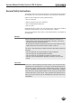
System Manual Safety System CES-A-S5H01 Possible combinations for CES components 098775 CES-A-BPA All items CES-A-NBA-...
System Manual Safety System CES-A-S5H01 General Safety Instructions The number of teach-in and switching operations is saved in the internal memory in the evaluation unit. If necessary, this memory can be read by the manufacturer.
System Manual Safety System CES-A-S5H01 System Description The safety system CES-A-S... complies with the following safety requirements: Category 4, PLe according to EN ISO 13849-1 Proximity device with self-monitoring type PDF-M according to EN 60947-5-3. Redundant design of the circuit in the evaluation unit with self-monitoring. As a result, the safety system is still effective even if a component fails.
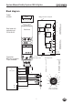
System Manual Safety System CES-A-S5H01 Block diagram Transponder Output circuit for output A: 3 +UB Safety CPU A Read coil Read head with evaluation unit CES-A-S5H-01 1 +LA LA Safety DDSP Read head 4 Double dynamic safety path Safety CPU B 5 +LB LB 8 D0 9 State Dog CPU YE Out RD ERROR EUCHNER Safety switch 11 Screen bonding clamp D0 D1 D2 LA D3 Contactor X +LB D2 D3 Plug housing or Screen bonding clamp cable screen Connection: M23 plug connector 12-pin, screened +LA D1 10
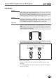
System Manual Safety System CES-A-S5H01 Changing the approach direction Caution! Risk of damage to equipment as a result of trapped cables. Make sure that the cables are not trapped or torn off when the approach direction is changed. The active face of the read head can be adjusted in 5 directions. The face is marked with the EUCHNER logo. The center of the circle corresponds to the middle of the read head. 1. Remove clamp from read head by undoing the screws (1). .
System Manual Safety System CES-A-S5H01 Installation Caution! Safety switches must not be bypassed (bridging of contacts), turned away, removed or otherwise rendered ineffective. On this topic pay attention in particular to the measures for reducing the possibility of bypassing according to EN 1088:1995.A2:2008, sec. 5.7. Caution! Risk of damage to equipment as a result of incorrect installation. Safety switches must not be used as a mechanical end stop.
System Manual Safety System CES-A-S5H01 Actuator and safety switch must be fitted so that the front faces are at the minimum switch-on distance 0.8 x Sao or closer (see section Operating distances). To avoid entering the area of possible side lobes, a minimum distance is to be maintained in case of a side approach direction. See section Typical operating distance for the related actuator. when the safety guard is open up to the distance Sar (assured switch-off distance), a hazard is excluded.
System Manual Safety System CES-A-S5H01 Electrical Connection Warning! Loss of the safety function due to incorrect connection. Not suitable for safety relays that realize short-circuit monitoring with different potentials (0 V/24 V). The voltage at +LA/+LB must correspond to the information in the technical data. +24 V A1 +UB CES-A-S5... +LA S11 LA S12 +LB S22 LB S21 -LAB 0V 0V A2 OUT Warning! In case of an error, loss of the safety function through incorrect connection.
System Manual Safety System CES-A-S5H01 Warning! Electrical connection may only be performed by authorized personnel trained in EMC and with the device and wiring isolated. The device is fully encapsulated, it is therefore not possible to remove the lid from the housing. Important! If the device does not appear to function when operating voltage is applied (e.g. green STATE LED does not illuminate or flash), the safety switch must be returned unopened to the manufacturer.
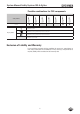
System Manual Safety System CES-A-S5H01 Safety switch CES-A-S5... Voltage drop as a function of switching current and cable length (examples) Switching current Cable length "l" Voltage drop Max. voltage drop Max. voltage drop [mA] [m] Output [V] Cable [V] Total [V] 6 (safety control system with pulsed signals) 1 -100 1,4 0,1 1,5 101 - 300 1,4 0,4 1,8 1 - 15 1,5 0,2 1,7 50 (safety relay) 400 (e. g.
System Manual Safety System CES-A-S5H01 Correct connection Important! To ensure safety, both safety outputs (LA and LB) must be evaluated. To achieve category 4 according to EN ISO 13849-1, it is necessary to moni- To the control system + 24 V M + 24 V + 24 V Application +LA Safety outpu LA LA +LB LB -LAB Safety output LB Monitoring output (no safety fnction!) OUT +UB 0V CES-A-S5... tor the downstream contactors.
System Manual Safety System CES-A-S5H01 Connection example CES-A-S5H-01 +24V DC -F1 -F2 Safety - PLC with static / dynamic signals Power Supply O1 Pulsed output O2 Pulsed Output A1 I1 Input 2 +LA 4 +LB I2 Input 3 +UB EUCHNER Read head CES-A-S5H-01 090640 I3 Input LA 1 I4 Input LB 5 D3 11 D2 10 D1 9 D0 8 0V 6 I5 Input I6 Input GND Important! To achieve category 4 according to EN ISO 13849-1, it is necessary to monitor the downstream contactors (not shown here).
System Manual Safety System CES-A-S5H01 Pin assignment safety switch CES-A-S5... 1 2 3 4 5 6 LA + LA + UB + LB LB 0 V 8 7 8 9 10 11 12 NC D0 D1 D2 D3 NC 9 1 12 10 2 7 3 6 11 5 4 View of connection side of the device The screen on the connection cable is connected internally to the device screen bonding clamp via the knurled nut on the M12 plug connector.
System Manual Safety System CES-A-S5H01 Teach-in function for actuator The safety actuator must be allocated to the evaluation unit using a teach-in function before the system forms a functional unit. During a teach-in operation, the safety outputs and the door monitoring output OUT are LOW, i.e. the system is in the safe state. Important! Repeated teach-in of the same actuator on the same evaluation unit is not possible.
System Manual Safety System CES-A-S5H01 Functional check After installation and any fault, the safety function must be fully checked. Proceed as follows: Warning! Danger of fatal injury as a result of faults in installation and functional check. Before carrying out the functional check, make sure that there are no persons in the danger area. Observe the valid accident prevention regulations. 1. Switch on operating voltage. The safety switch carries out a self-test.
System Manual Safety System CES-A-S5H01 System Status Table Normal operation Setup State indication Fault display Operating fault OUT/ERROR (red) OUT/ERROR (yellow) STATE (green) Safety outputs LA and LB Operating mode Actuator position LED display State See truth table on page 20 and section LED displays on page 16 open off 4 Hz Initial setup after delivery, ready for first teach-in operation closed off 1 Hz (60 s) Teach-in operation closed off X off 3x+ Indication after 1st to 5
System Manual Safety System CES-A-S5H01 Truth table Actuator Safety outputs Data outputs/LED displays LA LB D3 D2 D1 D0 No actuator 0 0 0 0 0 0 Safety actuator 1 1 0 0 0 1 Actuator 2 0 0 0 0 1 0 Actuator 3 0 0 0 0 1 1 Actuator 4 0 0 0 1 0 0 Actuator 5 0 0 0 1 0 1 Actuator 6 0 0 0 1 1 0 Actuator 7 0 0 0 1 1 1 Actuator 8 0 0 1 0 0 0 Actuator 9 0 0 1 0 0 1 Actuator A 0 0 1 0 1 0 1 Actuator B 0 0 1 0 1 Actuator C 0 0
System Manual Safety System CES-A-S5H01 Technical Data Note If a product data sheet is included with the product, the information on the data sheet applies in case of discrepancies with the operating instructions.
System Manual Safety System CES-A-S5H01 Technical Data Value Parameter min.
System Manual Safety System CES-A-S5H01 Actuator CES-A-BPA Cube-shaped design 40 x 40 mm Dimension drawing CES-A-BPA 10 0 Ø 5,2 40 - 0,25 4 30 ±0,1 CES-A-BPA-098775 IP67 CD Active face Active face 2 safety screws M4 x 14 are supplied Technical Data Parameter Value typ. PPS 40 x 40 x 10 0,025 IP67/IP69K Active face opposite read head Inductive via read head min. Housing material Dimensions Weight Ambient temperature Degree of protection Installation position Power supply -25 max.
System Manual Safety System CES-A-S5H01 Typical operating distance Only in conjunction with actuator CES-A-BPA on surface mounting. Y 45 40 35 30 25 20 15 10 5 51 -45 5 45 40 35 30 25 1 1 0 20 5 01 52 02 53 03 54 04 5 Z X -45 For a side approach direction for the actuator and read head, a minimum distance of s = 6 mm must be maintained so that the operating distance of the side lobes is not entered. Operating distance for center offset m = 0 Value Parameter min. typ. max.
System Manual Safety System CES-A-S5H01 Actuator CES-A-BBA Cube-shaped design 42 x 25 mm CES-A-BCA suitable for use in aggressive media (e.g. acids, alkalis) Approvals Dimension drawing CES-A-BBA 12 25 CES-A-B 071840 ø8 ø4,5 42 32 ±0,1 Active face 4,6 Active face 2 safety screws M4 x 14 are supplied Technical Data Parameter Value typ. min.
System Manual Safety System CES-A-S5H01 Position actuator CES-A-NBA-. in combination with safety switch CES-A-S5H-01 Approvals Dimension drawing 32 ±0,15 AB Ø 8 <25> Ø 4,5 Active face 4,6 <42> 0 12 - 0,1 2 safety screws M4 x 14 are supplied Technical Data Value min. typ. max. Fortron, reinforced thermoplastic, fully encapsulated, green 42 x 25 x 12 0,02 -25 +70 IP67 Active face opposite read head Inductive via read head 4 bits (1 BCD digit) approx.
System Manual Safety System CES-A-S5H01 Typical operating distance Only in combination with actuator CES-A-BBA or CES-A-NBA Y 30 25 20 -30 15 10 5 5 5 10 10 15 15 20 20 25 25 30 X Z -30 For a side approach direction for the actuator and safety switch, a minimum distance of s = 4 mm must be maintained so that the operating distance of the side lobes is not entered. Operating distance for center offset m = 0 1) Value Parameter min. Assured switch-on distance Sao typ. max.
System Manual Safety System CES-A-S5H01 Inspection and Service Warning! Loss of the safety function because of damage to the device. In case of damage, the related safety component must be replaced. The replacement of individual parts in a safety component is not permitted.
System Manual Safety System CES-A-S5H01 Declaration of Conformity 29
System Manual Safety System CES-A-S5H01 30
System Manual Safety System CES-A-S5H01 31
Euchner GmbH + Co. KG Kohlhammerstraße 16 D-70771 Leinfelden-Echterdingen info@euchner.de www.euchner.de Issue: 095710-08-01/12 Title: System Manual Safety System CES-A-S5H-01 (Translation of the Original Operating Instructions) Copyright: © EUCHNER GmbH + Co. KG, 01/2012 Subject to technical modifications; no responsibility is accepted for the accuracy of this information. More than safety.