
User guide

System Manual Safety System CES-A-C5...
19
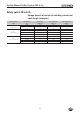
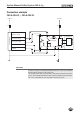
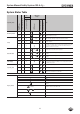
System Status Table
Operating mode
Actuator/
Guard position
Safety outputs LA and LB
PLC
LED display
Output
State
Output
OUT (status signal)
STATE (green)
OUT/ERROR (yellow)
OUT/ERROR (red)
Normal operation
closed on 1 Normal operation, door closed
open off 0 Normal operation, door open
Setup
open off 0 4 Hz Initial setup after delivery, ready for first teach-in operation
closed off 0
1 Hz
(60 s)
Teach-in operation
closed off 0
Positive acknowledgement of completion of teach-in operation
To activate the actuator code from the teach-in operation in the evalu-
ation unit, the operating voltage must then be switched off at the
evaluation unit for min. 3 seconds.
State indication
X off 0
3 x +
Indication after 1st to 5th teach-in operation
X off 0
2 x +
Indication of the remaining teach-in operations after the 6th teach-in
operation
X off 0
1 x +
Indication of the remaining teach-in operations after the 7th teach-in
operation
X off 0 Device cannot perform any further teach-in operation
Fault display
X off 0
Device-internal component failure or
excessively high interference (EMC) or short circuit/external power at
the LA/LB safety output
Operating fault
closed off 0
1 x
Incorrect 9th teach-in operation
closed off 0
2 x
Incorrect teach-in operation for an old actuator
closed off 0
3 x Negative acknowledgement for teach-in operation. Actuator was held
in front of the read head for less than 60 s
Key to symbols
N 0 Volt or not connected
1 24 Volt
0 0 Volt
LED is not lit
LED is lit
15 Hz (8 s)
LED flashes for 8 seconds with 15 Hz
3 x +
LED flashes three times and then lights up continuously
3 x
LED flashes three times, and this is then repeated
X Any state