Operating instructions Non-contact safety system CES-A-ABA-01/CES-A-ABA-01B (Unicode) More than safety.
Operating Instructions Safety System CES-A-ABA-01/CES-A-ABA-01B Contents Correct Use Possible combinations for CES components 3 4 Exclusion of Liability and Warranty 4 General Safety Instructions 5 Function Block diagram 6 7 Installation 8 Electrical Connection Safety in case of faults Fusing of the power supply and the safety contacts.
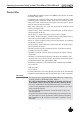
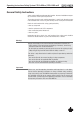
Operating Instructions Safety System CES-A-ABA-01/CES-A-ABA-01B Correct Use The Coded Electronic Safety switches series CES are safety devices for monitoring movable safety guards. In combination with a separating safety guard and the machine control, this safety component prevents dangerous machine movements from occurring while the safety guard is open. A stop command is triggered if the safety guard is opened during the dangerous machine function.
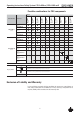
Operating Instructions Safety System CES-A-ABA-01/CES-A-ABA-01B Possible combinations for CES components 096327 CET-A-BWK-50X 095175 CEM-A-BH10 094805 CEM-A-BE05 098775 CES-A-BPA All items CES-A-NBA-... 098108 CES-A-BQA 077791 CES-A-BMB 084720 CES-A-BDA 088786 CES-A-BCA Read head 071840 Evaluation unit CES-A-BBA Actuator CES-A-LNA... All items CES-A-LNA-SC 077715 CES-A-ABA-01 071850 CES-A-LCA... All items CES-A-LMN-SC 077790 CES-A-LQA-SC 095650 CES-A-LNA...
Operating Instructions Safety System CES-A-ABA-01/CES-A-ABA-01B General Safety Instructions Safety switches fulfill personal protection functions. Incorrect installation or tampering can lead to severe injuries to personnel. The number of teach-in and switching operations is saved in the internal memory in the evaluation unit. If necessary, this memory can be read by the manufacturer.
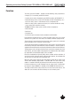
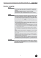
Operating Instructions Safety System CES-A-ABA-01/CES-A-ABA-01B Function The safety system CES-A-ABA... complies with the following safety requirements: Ì Category 3, PLe according to EN ISO 13849-1 Ì Proximity device with self-monitoring type PDF-M according to EN 60947-5-3. Ì Redundant design of the circuit in the evaluation unit with self-monitoring. As a result, the safety system is still effective even if a component fails.
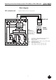
Operating Instructions Safety System CES-A-ABA-01/CES-A-ABA-01B Block diagram CES evaluation unit Illustration: Actuator not in the operating distance Screen connection brown white H11 24V H12 Read head SH1 0V TST Operation without external testing TST input not connected: DDSP CPU-A DDSP: Double Dynamic Safety Part with fault monitoring of the actuator, read head and the cable to the read head CPU-B KA KB 10k7 10k7 OUT ERR GND 13 Transponder Coded actuator 14 23 24 TST OUT ERR G
Operating Instructions Safety System CES-A-ABA-01/CES-A-ABA-01B Installation Caution! Safety switches must not be bypassed (bridging of contacts), turned away, removed or otherwise rendered ineffective. Ì On this topic pay attention in particular to the measures for reducing the possibility of bypassing according to EN 1088:1995.A2:2008, sec. 5.7. Ì The evaluation unit must be mounted in a control cabinet with a minimum degree of protection of IP 54.
Operating Instructions Safety System CES-A-ABA-01/CES-A-ABA-01B Note the following points: Ì Actuator and read head must be easily accessible for inspection and replacement. Ì The switching operation must only be triggered by the specific actuator designated for this purpose. Ì Actuator and read head must be fitted so that Ì the front faces are at the minimum switch-on distance 0.8 x Sao or closer (see section Operating distances).
Operating Instructions Safety System CES-A-ABA-01/CES-A-ABA-01B Electrical Connection Warning! In case of an error, loss of the safety function through incorrect connection. Ì To ensure safety, both safety outputs (13/14 and 23/24) must always be evaluated. Ì The monitoring output OUT must not be used as a safety output. Ì Lay the connection cables with protection to prevent the risk of short circuits. Caution! Risk of damage to equipment or malfunctions as a result of incorrect connection.
Operating Instructions Safety System CES-A-ABA-01/CES-A-ABA-01B Safety in case of faults Ì The operating voltage UB is reverse polarity protected. Ì The connections for the read heads, ERR and OUT are not short circuit-proof. Ì A short circuit between 13/14 and 23/24 can be detected only by means of external pulsing. Ì A short circuit in the cable can be excluded by laying the cable with protection. Fusing of the power supply and the safety contacts.
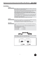
Operating Instructions Safety System CES-A-ABA-01/CES-A-ABA-01B Correct connection Important! Ì To ensure safety, both safety outputs (13/14 and 23/24) must be evaluated. Ì To achieve category 3 according to EN ISO 13849-1, it is necessary to moni- Application 23 Relay K B 24 + 24 V To the control system + 24 V 13 Relay K A 14 OUT 24 V + 24 V 0V CES-A-A BA... Monitoring output (no safety function!) tor the downstream contactors.
Operating Instructions Safety System CES-A-ABA-01/CES-A-ABA-01B Connection example CES-A-ABA... (example based on CES-A-ABA-01B) 24 VDC Transponder -F1 -F2 Readhead 0V 24V L1 -K2 SH1H11H12 L2 L3 13 23 33 14 24 34 EUCHNER CES-A-ABA-01B 083513 TST OUT ERR GND 13 -K1 23 14 24 33 34 23 24 13 14 -M1 -V1 -K1 -V2 M 3~ -K2 GND Important! To achieve category 3 according to EN ISO 13849-1, it is necessary to monitor the downstream contactors (not shown here).
Operating Instructions Safety System CES-A-ABA-01/CES-A-ABA-01B Setup LED indicators STATE LED green Normal operation Flashing Teach-in operation (for further signal function see status table) OUT LED yellow Valid actuator detected ERROR LED red - Test input activated - Internal electronics fault - Invalid teach-in operation (see status table) Reset In case of operating faults, the evaluation unit can be reset to the operating state by interrupting the power supply for approx. 10 seconds.
Operating Instructions Safety System CES-A-ABA-01/CES-A-ABA-01B Carrying out teach-in for first actuator (state on delivery) 1. Apply the operating voltage to the evaluation unit Ì green LED flashes fast (approx. 4 Hz) 2. Move actuator to the read head (observe distance < Sao) Ì teach-in operation starts, green LED flashes slowly (approx. 1 Hz) 3. Teach-in operation completed (after 60 seconds) Ì green LED goes out 4.
Operating Instructions Safety System CES-A-ABA-01/CES-A-ABA-01B Functional check After installation and any fault, the safety function must be fully checked. Proceed as follows: Warning! Danger of fatal injury as a result of faults in installation and functional check. Ì Before carrying out the functional check, make sure that there are no persons in the danger area. Ì Observe the valid accident prevention regulations. 1. Switch on operating voltage. Ì The safety switch carries out a self-test.
Operating Instructions Safety System CES-A-ABA-01/CES-A-ABA-01B System Status Table Actuator/door position Safety outputs A and B TST OUT (status signal) ERR closed on N 1 0 Normal operation, door closed open off N 0 0 Normal operation, door open open off N 0 0 4 Hz Initial setup after delivery, ready for first teach-in operation closed off N 0 0 1 Hz (60 s) Teach-in operation LED display, output ERROR (red) Output OUT (yellow) In- STATE (green) Operating mode PLC Stat
Operating Instructions Safety System CES-A-ABA-01/CES-A-ABA-01B Technical Data Note! If a product data sheet is included with the product, the information on the data sheet applies in case of discrepancies with the operating instructions. Evaluation unit CES-A-ABA...
Operating Instructions Safety System CES-A-ABA-01/CES-A-ABA-01B Technical Data Value Parameter Unit min. typ. max. Plastic PA6.6 114 x 99 x 22.5 0.2 -20 +55 80 IP20 2 DIN rail 35 mm according to EN 60715 1 read head per evaluation unit 0.14 2.5 21 24 27 Operation only with UL Class 2 power supply, or equivalent measures 150 0.
Operating Instructions Safety System CES-A-ABA-01/CES-A-ABA-01B Read head CES-A-LNA...
Operating Instructions Safety System CES-A-ABA-01/CES-A-ABA-01B Pin assignment Read head with connection cable Screen BN Read head WH H11 H12 SH1 Evaluation unit CES-A-ABA... Technical Data Parameter Value min. typ. Unit max. Housing material Fortron, reinforced thermoplastic, fully encapsulated Dimensions 42 x 25 x 12 Weight (incl. 10 m cable) 0.
Operating Instructions Safety System CES-A-ABA-01/CES-A-ABA-01B Ordering table Series Cable/connection type V Cable PVC CES-A-LNA... P Cable PUR 22 Cable length "l" [m] Order no.
Operating Instructions Safety System CES-A-ABA-01/CES-A-ABA-01B Read head CES-A-LNA-SC Ì Cube-shaped design 42 x 25 mm Ì M8 plug connector (snap-action and screw terminals) Ì In combination with CES-A-BBA actuator Approvals Dimension drawing 32,6 42 12 32 ±0,1 6,8 4,6 8 4,5 10 26,5 CES-A-L 077715 A0 25 CES-A-L 077715 3 A0 Active face 20,1 1 min.
Operating Instructions Safety System CES-A-ABA-01/CES-A-ABA-01B Pin assignment Read head with plug connector WH Screen BN H11 H12 4 3 1 View on the plug connector of the read head SH1 Evaluation unit CES-A-ABA... Technical Data Parameter Value min. typ. Unit max. Housing material Fortron, reinforced thermoplastic, fully encapsulated Dimensions 42 x 25 x 12 Weight (incl. 10 m cable) 0.
Operating Instructions Safety System CES-A-ABA-01/CES-A-ABA-01B Ordering table Series Order no.
Operating Instructions Safety System CES-A-ABA-01/CES-A-ABA-01B Read head CES-A-LCA... Ì Cube-shaped design 42 x 25 mm Ì Plastic PE-HD housing material, suitable for use in aggressive media (e.g. ac- Approvals ids, alkalis) Ì In combination with CES-A-BCA actuator Dimension drawing 48 14 42 12 4,6 31 25 8 4,5 32 ± 0,1 Flat seal Active face Active face l 2 safety screws M4 x 14 are supplied Note The flat seal provided must be used during assembly.
Operating Instructions Safety System CES-A-ABA-01/CES-A-ABA-01B Pin assignment Read head with connection cable Screen BN Read head WH H11 H12 SH1 Evaluation unit CES-A-ABA... Technical Data Parameter Value min. typ. Unit max. Housing material Plastic PE-HD without reinforcement, fully encapsulated Flat seal material Fluororubber 75 FPM 4100 Dimensions 42 x 25 x 12 Weight (incl. 10 m cable) 0.
Operating Instructions Safety System CES-A-ABA-01/CES-A-ABA-01B Ordering table Series Cable/connection type Cable length "l" [m] Order no. / item CES-A-LCA...
Operating Instructions Safety System CES-A-ABA-01/CES-A-ABA-01B Read head CES-A-LQA-SC Ì Cube-shaped design 50 x 50 mm Ì M8 plug connector (snap-action and screw terminals) Dimension drawing 0 Ø 4,5 0 50 - 0,25 M 8x1 7 40 ±0,15 6 Active face Typical operating distance Y 30 20 -30 10 10 10 20 20 30 30 Z X -30 With actuator CES-A-BBA or CES-A-BCA Y 30 20 10 10 10 20 20 30 X 30 Z with actuator CES-A-BQA on evaluation unit CES-A-ABA-01B 29 40 ±0,15 50 - 0,25 20,2 20 Approval
Operating Instructions Safety System CES-A-ABA-01/CES-A-ABA-01B Pin assignment Read head with connection cable Screen BN WH H11 H12 4 1 3 Read head SH1 Evaluation unit CES-A-ABA-... Technical Data Parameter Value min. Housing material typ. Unit max. Fortron, reinforced thermoplastic, fully encapsulated Dimensions 50 x 50 x 20.2 Weight mm 0.
Operating Instructions Safety System CES-A-ABA-01/CES-A-ABA-01B Read head CES-A-LMN-SC Ì Cylindrical design M12 Ì M8 plug connector (snap-action and screw terminals) Ì In combination with CES-A-BMB actuator Approvals Dimension drawing R eading distance s 17 4 35 m M8x1 Centre offset 19,7 M12x1 32 1) connected 5 Active face 1) 8 30 1) Clear zone (area of the active face without metal housing) 37 Note The read head is allowed to be installed as a maximum up to the clear zone (area of the ac
Operating Instructions Safety System CES-A-ABA-01/CES-A-ABA-01B Pin assignment Read head with plug connector WH Screen BN H11 H12 4 3 1 View on the plug connector of the read head SH1 Evaluation unit CES-A-ABA... Technical Data Parameter Value min. Unit typ. Housing material max. Nickel-plated CuZn housing sleeve Plastic PBT GF20 cap Dimensions M12 x 1, length 38 Weight (incl. 10 m cable) mm 0.
Operating Instructions Safety System CES-A-ABA-01/CES-A-ABA-01B Actuator CES-A-BBA/CES-A-BCA Ì Cube-shaped design 42 x 25 mm Ì CES-A-BCA suitable for use in aggressive media (e.g. acids, alkalis) Ì In combination with read head CES-A-LNA.../CES-A-LCA...
Operating Instructions Safety System CES-A-ABA-01/CES-A-ABA-01B Actuator CES-A-BQA Ì Cube-shaped design 50 x 50 mm Dimension drawing CES-A-BQA 0 50 - 0,25 Ø 4,5 0 50 - 0,25 40 ±0,15 20,2 40 ±0,15 6 Active face Technical Data Value Parameter min. Housing material typ. Unit max. Fortron, reinforced thermoplastic, fully encapsulated Dimensions 50 x 50 x 20.2 Weight mm 0.
Operating Instructions Safety System CES-A-ABA-01/CES-A-ABA-01B Actuator CES-A-BDA Ì Round design ∅ 20 mm Ì In combination with read head CES-A-LNA.../CES-A-LCA... Dimension drawing Active face Active face 20 2,2 Technical data Value Parameter min. typ. Housing material Plastic PC Dimensions ∅ 20 x 2.2 Weight max. mm 0.
Operating Instructions Safety System CES-A-ABA-01/CES-A-ABA-01B Actuator CES-A-BMB Ì Cylindrical design M12 x 75 Ì In combination with evaluation units CES-A-A..., read head CES-A-LMN-SC (operating distance on request for read head CES-A-LNA.../LCA...) Dimension drawing 6 11 M12x0,75 0,80 Active face Notes Ì The actuator can be screwed into the M12 x 0.75 thread provided with the aid of an insertion tool (Order No. 037 662). Ì Flush installation of the actuator in steel is allowed.
Operating Instructions Safety System CES-A-ABA-01/CES-A-ABA-01B Inspection and service Warning! Loss of the safety function because of damage to the device. In case of damage, the related safety component must be replaced. The replacement of individual parts in a safety component is not permitted.
Operating Instructions Safety System CES-A-ABA-01/CES-A-ABA-01B Declaration of Conformity 38
Operating Instructions Safety System CES-A-ABA-01/CES-A-ABA-01B 39
Operating Instructions Safety System CES-A-ABA-01/CES-A-ABA-01B 40
Operating Instructions Safety System CES-A-ABA-01/CES-A-ABA-01B 41
Euchner GmbH + Co. KG Kohlhammerstraße 16 D-70771 Leinfelden-Echterdingen info@euchner.de www.euchner.de Issue: 071873-14-10/13 Title: Operating Instructions Safety System CES-A-ABA-01/CES-A-ABA01B (translation of the original operating instructions) Copyright: © EUCHNER GmbH + Co. KG, 10/2013 Subject to technical modifications, all data supplied without liability. More than safety.