
Safety Monitor for 2 AS-i circuits

AS-i Safety Monitor for 2 AS-i circuits
Diagnostics for AS-i Monitor and networking using AS-i Master
Subject to reasonable modifications due to technical advances Id.-No.: 103336 Issue date - 24.10.2008 EUCHNER GmbH + Co. KG
87
Kohlhammerstraße 16 • D-70771 Leinfelden-Echterdingen Tel. +49/711/75 97-0 • Fax. +49/711/753316
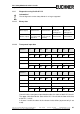
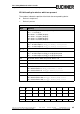
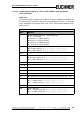
Bit field coding for devices which are present:
The numbers indicate the position of the bit for the corresponding device.
0: Device is not present
1: Device is present
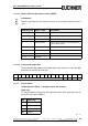
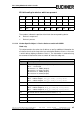
11.4.3.4 Vendor Specific Object 9 - Device Colors at switch off OSSD 1
Read only.
This object contains the colors for all devices as well as additional information for
all release circuits at the time of the last switch-off of Release Circuit 1. Also sent
is which devices belong to Release Circuit 1. The information is retrieved using
the command "Get Device Colors at switch off" from the safety unit.
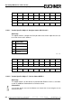
Byte
2
7
2
6
2
5
2
4
2
3
2
2
2
1
2
0
176543210
2 1514131211109 8
……
32 255 254 253 252 251 250 249 248
Tab. 11-18.
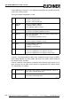
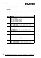
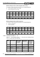
Coding for the states and colors
Byte Meaning
1 Bit 0 0=Configuration mode, 1=protecting mode
Bit 3 ... 1 reserved, 0
Bit 4 status 1.Y1, EDM1 (0=open)
Bit 5 status 1.Y2, Start1 (0=open)
Bit 6 status 2.Y1, EDM2 (0=open)
Bit 7 status 2.Y2, Start2 (0=open)
2 Relay status, Output 1+2
Bit 3 ... 0 State Output 1, diag_pc.ossd[0].relay-state
Bit 7 ... 4 State Output 2, diag_pc.ossd[1].relay-state
3 ... 8 ...
9 Relay status, Output 15+16
Bit 3 ... 0 State Output 15, diag_pc.ossd[14].relay-state
Bit 7 ... 4 State Output 16, diag_pc.ossd[15].relay-state
10 Bit field for devices which are present. Device 7 ... 0
11 ... 40 ...
41 Bit field for devices which are present. Device 248 ... 255
42 Bit field for devices which changed in the last step. Device 7 ... 0
Tab. 11-19.