
Safety Monitor for 2 AS-i circuits

AS-i Safety Monitor for 2 AS-i circuits
Diagnostics for AS-i Monitor and networking using AS-i Master
Subject to reasonable modifications due to technical advances Id.-No.: 103336 Issue date - 24.10.2008 EUCHNER GmbH + Co. KG
85
Kohlhammerstraße 16 • D-70771 Leinfelden-Echterdingen Tel. +49/711/75 97-0 • Fax. +49/711/753316
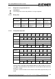
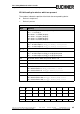
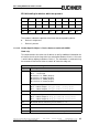
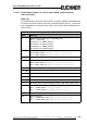
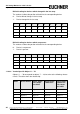
Bit field coding for devices which are present:
The numbers indicate the position of the bit for the corresponding device.
0: Device is not present
1: Device is present
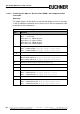
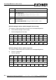
Coding for the states and colors
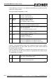
Byte Meaning
1 Bit 0 0=Configuration mode, 1=protecting mode
Bit 3 ... 1 reserved, 0
Bit 4 State 1.Y1, EDM1 (0=open)
Bit 5 State 1.Y2, Start1 (0=open)
Bit 6 State 2.Y1, EDM2 (0=open)
Bit 7 State 2.Y2, Start2 (0=open)
2 Relay status, Output 1+2
Bit 3 ... 0 State Output 1, diag_pc.ossd[0].relay-state
Bit 7 ... 4 State Output 2, diag_pc.ossd[1].relay-state
3 ... 8 ...
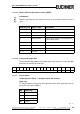
9 Relay status, Output 15+16
Bit 3 ... 0 State Output 15, diag_pc.ossd[14].relay-state
Bit 7 ... 4 State Output 16, diag_pc.ossd[15].relay-state
10 Bit field for devices which are present. Device 7..0
11 ... 40 ...
41 Bit field for devices which are present. Device 248..255
42 Color - Device 1+2
Bit 3..0 Color Device 1, diag_pc.device[0].color
Bit 7..4 Color Device 2, diag_pc.device[1].color
43 ... 168 ...
169 Device 255+256
Bit 3..0 Color Device 255, diag_pc.device[254].color
Bit 7..4 Color Device 256, diag_pc.device[255].color
Tab. 11-15.
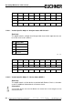
Byte
2
7
2
6
2
5
2
4
2
3
2
2
2
1
2
0
176543210
2 1514131211109 8
……
32 255 254 253 252 251 250 249 248
Tab. 11-16.