
Safety Monitor for 2 AS-i circuits

AS-i Safety Monitor for 2 AS-i circuits
Diagnostics for AS-i Monitor and networking using AS-i Master
Subject to reasonable modifications due to technical advances Id.-No.: 103336 Issue date - 24.10.2008 EUCHNER GmbH + Co. KG
81
Kohlhammerstraße 16 • D-70771 Leinfelden-Echterdingen Tel. +49/711/75 97-0 • Fax. +49/711/753316
11.4 Diagnostics using Profile S-7.5.5
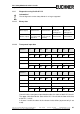
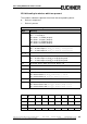
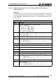
11.4.1 Binary data
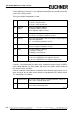
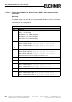
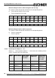
11.4.2 Transparent input data
Channel 0 of the transparent input data describes the status of both AS-i circuits.
The upper 8 bits describe the status of the AS-i 2 circuit and the lower 8 bits that
of the AS-i 1 circuit.
In channel 1 and 2 the colors of the release circuits follow (at present only 2 are
used).
Information!
The old diagnostics for the Safety Monitor is no longer supported.
D3 D2 D1 D0
Monitor->
Master (input)
Serial
communication
Serial
communication
1: Output 2 either
turned off or
flashing green
1: Output 1 either
turned off or
flashing green
Master->
Monitor (output)
Change from 0 to
1 resets the fault
lamp AS-i 2
Change from 0 to
1 resets Circuit 1
fault lamp
Serial
communication
Serial
communication
Tab. 11-4.
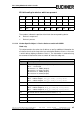
Channel
2
15
2
14
2
13
2
12
2
11
2
10
2
9
2
8
0AS-i circuit 2
AU RD YE GN UA DA EF
1 Status OSSD 4 Status OSSD 3
2 Status OSSD 8 Status OSSD 7
3 OSSD 8 OSSD 7 OSSD 6 OSSD 5
RF YF RF YF RF YF RF YF
Tab. 11-5.
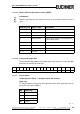
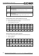
Channel
2
15
2
14
2
13
2
12
2
11
2
10
2
9
2
8
0AS-i circuit 1
RD YE GN UA DA EF
1 Status OSSD 2 Status OSSD 1
2 Status OSSD 6 Status OSSD 5
3 OSSD 4 OSSD 3 OSSD 2 OSSD 1
RF YF RF YF RF YF RF YF
Tab. 11-6.