
Safety Monitor for 2 AS-i circuits

36
Subject to reasonable modifications due to technical advances Id.-No.: 103336 Issue date - 24.10.2008 EUCHNER GmbH + Co. KG
Kohlhammerstraße 16 • D-70771 Leinfelden-Echterdingen Tel. +49/711/75 97-0 • Fax. +49/711/753316
AS-i Safety Monitor for 2 AS-i circuits
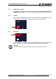
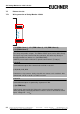
Electrical connection
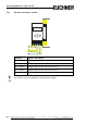
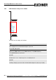
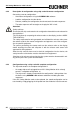
7.8.2 LED indicators safety unit in 103303
The LED’s on the safety unit indicate:
1.Y1
Aux
2.Y1
K1
K3
1.Y2
2.Y2
K2
K4
2.13
+
24 V
2.Y1
0 V
+
1.13
2.Y2
1.Y2
2.14
+
4.14
+
1.14
1.Y1
3.14
Aux
24 V supply for the semiconductor outputs is present.
1Y.1, 1Y2, 2Y.1, 2Y.2
Input 1.Y1 (EDM 1/Start 1), 2.Y1 (EDM 2/Start 2), 1.Y2 (EDM 3/Start 3),
2.Y2 (EDM 4/Start 4) is turned on.
K1, K2
Contact sets 1.13, 1.14 (K1) resp. 2.13, 2.14 (K2) closed.
K3, K4
Auxiliary voltage is present on the semiconductor output 3.14 (K3) resp.14 (K4).