
Operating instructions


Tap Voltage Range
240 Volt 253 - 216
208 Volt 220 - 187
Seven (7) conductor thermostat wires should be run from the
thermostat location to the unit. Thermostat wire should be sized as
shown on the table below.
Refer to wiring diagrams on for connection details.
STAGING OF ELECTRIC HEAT
All H Series units with electric heat assemblies are wired for two-
stage heat in normal operation. Units over 10 kW resistance heat
also have an additional stage for emergency heat. The first stage is
refrigerant heat (Y and G terminals are energized and O terminal is
de-energized). The second stage is auxiliary resistance heat (W is
energized). The third stage is emergency heat (E and W terminals
are energized). H Series units are equipped with an emergency heat
lock-out relay. This will disable the compressor when the E terminal
is energized. Do not install a jumper between the W and E terminals.
This would keep the compressor contacts from being energized and
prevent the compressor from operating.
H SERIES UNITS ARE FOR USE IN
SINGLE-STORY BUILDINGS ONLY
1. As previously stated, the wall that the unit is to be installed
onto MUST be strong enough to support the unit under the
condition for which it will be used. For example, a unit to be
installed on a building that is intended to be transported will
require more wall strength than a unit installed at a
permanent site. Existing walls may need additional
reinforcement. NEVER RELY ON EXTERIOR SIDING OR
PLYWOOD TO SUPPORT THE UNIT. Figure 2 below
represents a typical installation of a single-story stud wall at a
permanent site. Since building materials and techniques vary
with regions and intended use, a building contractor and/or
local building code official MUST be consulted for suitable
construction methods.
2. Locate and attach the lower mounting bracket in the desired
location on the building.
3. Apply a suitable caulk across the entire length of the top rain
flashing and side mounting flanges.
4. Remove the flanges on both ends of the pallet and slide the
unit approximately 2” off the rear of pallet. Lift unit gently into
location with fork truck, taking care to align unit with lower
mounting bracket.
5. While allowing a small portion of weight on the lower bracket,
push the unit against the wall and fasten appropriately.
J. UNIT INSTALLATION
Wire Gauge Maximum Length
20 45'
18 60'
16 100'
14 160'
12 250'
4
The installer MUST check available power to make certain it
matches the unit nameplate rating and that constant voltage can be
maintained to the unit. Unsatisfactory and unsafe performance
could otherwise result. The local power company should be
contacted about questions concerning power supply.
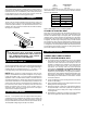
These units are standard equipped from the factory with a unit
disconnect. This is in the form of a circuit breaker (230V models) or
a disconnect (460V models). If an optional electric heat kit is to be
installed, follow the instructions included with the heater assembly.
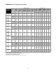
See Figure 1 for reference.
The line voltage electrical service can be routed through the right side
panel, the right side of the back panel, or left side panel. Each area is
supplied with two line voltage knock-outs (
1
/2" –
3
/4" and 1" – 1
1
/4").
Low voltage wiring can be routed through the right side panel.
NOTE: When routing line voltage through the return air com-
partment, conduit MUST be used (even though this is a dry area) to
comply with the NEC code. A 1
1
/4" PVC conduit is supplied for this
application. Refer to the ELECTRICAL tables for minimum wire size
and maximum breaker size. All wire sizes listed under the dual-feed
circuit column are based on no more than three (3) conductors in the
same conduit. If two circuits or more than three (3) conductors are to
be routed in the same conduit, the ampacity of the wire size listed
MUST be derated. Refer to Article 310 of the NEC code for
adjustment factors. Be sure to install a ground wire of the proper
size to the unit’s equipment ground lug.
230 volt, 1- and 3-phase units are equipped with dual-primary
voltage transformers for 208/240 volt operation. These models are
factory wired to the 240 volt tap. For 208 volt operation, connect the
factory-installed black wires from the 240 volt tap to the 208 volt tap.
The acceptable voltage range of the tap is as follows:
FIGURE 1
Electrical Box
Breaker
Breaker Mount
F. ELECTRICAL POWER
G. BREAKER/DISCONNECT ASSEMBLY
WARNING:
ELECTRICAL EQUIPMENT SHOULD
BE INSTALLED BY A QUALIFIED, LICENSED
ELECTRICIAN. IMPROPER ELECTRICAL HOOK-UP
MAY DAMAGE EQUIPMENT, CAN CREATE A
HAZARD, AND WILL VOID WARRANTY.
!
H. ELECTRICAL HOOK-UP
I. LOW VOLTAGE WIRING