Installation, Operation and Maintenance H SERIES Wallmount Heat Pumps R410A Series REV. 9/23/13 REV.
H SERIES WALLMOUNT HEAT PUMPS ! Your equipment is covered by a LIMITED WARRANTY against defects in material and workmanship. In all cases, the equipment MUST be installed in accordance with the installation instructions described in this manual. Set the thermostat to either HEAT or COOL as desired. Set the desired temperature on your thermostat dial and set the fan switch to “ON” (for continuous air circulation) or to “AUTOMATIC” (for air circulation only when the air conditioning system is operating).
7. Service clearance is 28" from the electrical box access panel located on the front of the unit and 28" from the center, upper, and lower front access panels. MAINTENANCE ! WARNING: SERIOUS INJURY MAY RESULT IF WATER SPRAY IS DIRECTED TOWARD LIVE ELECTRICAL CONNECTIONS OR POWER SOURCES. 8. The wall selected for unit installation MUST be able to or be made to safely support the weight of the unit. 9. Do NOT locate where heat, lint or exhaust fumes will be discharged on the unit (as from dryer vents).
Tap Voltage Range 240 Volt 253 - 216 208 Volt 220 - 187 Seven (7) conductor thermostat wires should be run from the thermostat location to the unit. Thermostat wire should be sized as shown on the table below. F. ELECTRICAL POWER The installer MUST check available power to make certain it matches the unit nameplate rating and that constant voltage can be maintained to the unit. Unsatisfactory and unsafe performance could otherwise result.
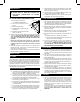
the time to be accumulated to initiate the defrost mode. The outdoor fan is wired through the N/C points of the control’s relay and the N/O points of the contactor. The fan motor will be energized whenever the contactor is energized (except during defrost). FIGURE 2 HEATING MODE Low-voltage terminal R is connected to Y,G and O, at the unit lowvoltage terminal board. Unit Model 18/24 30/36 48/60 A 35 39 42 The system reversing valve is powered during the heating mode.
EXPLODED PARTS DRAWING — 24 / 30 / 36 6
EXPLODED PARTS DRAWING — 42 / 48 / 60 7
REPLACEABLE PARTS LIST- H SERIES WALLMOUNT HEAT PUMPS 2 2 2 2 2 2 2 2 2 2 2 2 7 7 7 8 8 14 14 14 15 15 15 17/22 17/16A 3 3 3 4 4 5 5 5 5 6 6 9 9 10 10 10 11 11 11 12 12 12 13 13 13 1 1 1 18 21 22 22 22 22 23 23 23A 23B 24 24 24 24 24 25 25 25 25 25 25 25 26 26 26 27 27 27 28 28 PART NUMBER COMP-BZP24-001 COMP-BZP28-001 COMP-BZP28-003 COMP-BZP34-001 COMP-BZP34-003 COMP-BZP34-004 COMP-BZP44-001 COMP-BZP44-003 COMP-BZP44-004 COMP-BZP57-001 COMP-BZP57-003 COMP-BZP57-004 COND-H424 COND-H436 COND-H460 550505 55
REPLACEABLE PARTS LIST- H SERIES WALLMOUNT HEAT PUMPS 28 2 29 2 29 2 29 2 29 2 29 2 29 2 29 2 29 2 29 2 30 2 30 2 30 7 31 7 31A 7 32 8 32 8 32 14 32 14 33 14 34 15 34 15 34 15 35 17/22 35 17/16A 36 36 36 3 36 3 36 3 36 4 36 4 36 5 36 5 36 5 36 5 36 6 36 6 36 9 36 9 36 10 36 10 36 10 36 11 37 11 37 11 38 12 38 12 39 12 39 13 39 13 40 13 40 1 40 1 41 1 41 18 41 21 41 42 22 22 22 22 23 23 23A 23B 24 24 24 24 24 25 25 25 25 25 25 25 26 26 26 27 27 27 28 28 PART NUMBER 2023-5010 COMP-BZP24-001 2021-5011 COMP-BZ
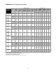
H Series Heat Pumps Electrical Data SINGLE-FIELD CIRCUIT VOLT/ PHASE MIN. CIRCUIT AMPACITY [2] MAX.
H pg 11.
H pg 12.
H pg 13.
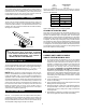
MODEL C D UNIT DIMENSIONS – LNOTES – P J K M N A B E F G H I S T U 24 36 34 18 5/8 281/16 12 201/2 8 17/8 20 289/16 11/8 711/2 21/2 101/2 181/2 261/2 347/8 11/8 16 32 30/36 40 38 18 5/8 281/2 14 18 8 17/8 28 289/16 11/8 711/2 21/2 101/2 181/2 261/2 39 11/4 181/4 363/8 2 48/60 431/8 41 16 30 10 21/4 30 361/2 87 21/2 101/2 181/2 261/2 42 11/8 193/4 391/2 61/2 24 271/2 A - FLANGE WIDTH R C K B - UNIT WIDTH 11/8 Q V W Y Z 2 9/16 291/2 2
14 15
The information in this manual supersedes and replaces the previous instruction/operation manual 678629-V V Series H with regards to H wallmount products. Illustrations, part numbers and others cover the general appearance of the units at the time of publication and the manufacturer reserves the right to make changes in design and construction at any time without notice.