
Manual

Front Panel Connectors and Controls
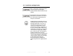
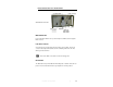
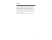
Model 3810/2 Front View
BNC
C
ONNECTOR
Connect the Model 3810/2 to the spectrum analyzer or EMI receiver through the
BNC connector.
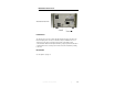
L
INE
S
ELECT
S
WITCH
Select the line to be monitored by the two-position selector switch. The line not
selected is internally terminated into 50 ohms. Switching between the two lines
will not generate transients.
Remove the BNC connection before disconnecting power.
RF
G
ROUND
The Model 3810/2 is provided with an RF bonding stud on both the front and rear
panels. The unit should be bonded to a ground plane in normal operation.
Installation and Application | 15