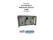
Model 3810/2 Line Impedance Stabilization Network (LISN) User Manual
ETS-Lindgren L.P. reserves the right to make changes to any product described herein in order to improve function, design, or for any other reason. Nothing contained herein shall constitute ETS-Lindgren L.P. assuming any liability whatsoever arising out of the application or use of any product or circuit described herein. ETS-Lindgren L.P. does not convey any license under its patent rights or the rights of others. © Copyright 1996–2010 by ETS-Lindgren L.P. All Rights Reserved.
Table of Contents Notes, Cautions, and Warnings ................................................ v Safety Symbol Definitions......................................................... v 1.0 Introduction .......................................................................... 7 ETS-Lindgren Product Information Bulletin ................................................... 7 2.0 Maintenance ......................................................................... 9 Service Procedures .........................
This page intentionally left blank.
Notes, Cautions, and Warnings Note: Denotes helpful information intended to provide tips for better use of the product. Caution: Denotes a hazard. Failure to follow instructions could result in minor personal injury and/or property damage. Included text gives proper procedures. Warning: Denotes a hazard. Failure to follow instructions could result in SEVERE personal injury and/or property damage. Included text gives proper procedures.
This page intentionally left blank.
1.0 Introduction The ETS-Lindgren Model 3810/2 Line Impedance Stabilization Network (LISN) is a two-channel low pass filter network designed to isolate the Equipment Under Test from an external power source while steering any radio frequency signals from the power line to a Model 3810/2 Front View 50-ohm port.
This page intentionally left blank.
2.0 Maintenance Before performing any maintenance, follow the safety information in the ETS-Lindgren Product Information Bulletin included with your shipment. Only trained service personnel should perform adjustments and/or service procedures. WARRANTY Inside the Model 3810/2 are LETHAL voltages with which you could come into contact. Capacitors inside the unit may still be CHARGED even when the unit is disconnected from power. Before Servicing contact ETS-Lindgren.
Maintenance of the Model 3810/2 is limited to external components such as cables or connectors. Clean the exterior of the cabinet using a damp cloth and mild cleaner. Always unplug the unit before cleaning. To prevent electrical shock, do not remove cover. If you have any questions concerning maintenance, contact ETS-Lindgren Customer Service.
3.
Physical Specifications 12 Height: 124 mm (4.9 in) Width: 218 mm (8.6 in) Depth: 381 mm (15.0 in) Weight: 5.4 kg (12.
4.0 Installation and Application Before connecting any components, follow the safety information in the ETS-Lindgren Product Information Bulletin included with your shipment. Overcurrent protection is not provided in the Model 3810/2. The unit must be connected to a power mains which has appropriately rated mains protection installed. The Model 3810/2 is provided with a protective earthing ground integral to the power cord.
The Model 3810/2 is provided with resistors to help bleed off high voltage transients, but it is advisable to connect the input and output connectors to their proper power lines and loads before connecting the monitor port to the measurement instrumentation; otherwise, power surges or transients can damage the test instrumentation mixers or attenuators.
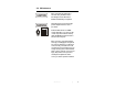
Front Panel Connectors and Controls Model 3810/2 Front View BNC CONNECTOR Connect the Model 3810/2 to the spectrum analyzer or EMI receiver through the BNC connector. LINE SELECT SWITCH Select the line to be monitored by the two-position selector switch. The line not selected is internally terminated into 50 ohms. Switching between the two lines will not generate transients. Remove the BNC connection before disconnecting power.
EARTH LINE CHOKE SWITCH The safety ground isolation choke selector switch switches the 1.6 mH earth line choke IN and OUT of the safety ground circuit. The ground choke is designed and manufactured with sufficient capacity to conduct the maximum current rating of the Model 3810/2 and at no time is the safety ground of the unit compromised. The earth line choke avoids a double RF ground connection (safety ground and measurement ground) in the conducted emissions test setup.
Back Panel Connectors Model 3810/2 Back View POWER INPUT The input power connection is made through the IEC-320 type power inlet. This three-wire input power connector is rated at 10 amperes maximum. In case of emergency, power can be removed from the unit by removing the power connection at the Model 3810/2 input. Alternately, a properly rated circuit breaker or switch which removes mains power from the unit can be installed in proximity to the unit. RF GROUND See description on page 15.
This page intentionally left blank.
5.0 Data Graphs of the calibration data for each measurement port of the Model 3810/2 Line Impedance Stabilization Network (LISN) are included with the unit. The graphs provide individual plots of both impedance and insertion loss data. Impedance is plotted in a semi-log format where frequency is displayed on the horizontal from 9 kHz to 30 MHz. The vertical has a range of 0 ohms to 100 ohms and represents the measured impedance of the unit.
This page intentionally left blank.
6.0 Schematic • Resistance values shown in ohms. • Ground choke select switch (S1) shown in the IN position. • Line monitor select switch (S2) shown in the L2 (NTL) position. • NEMA type output connector shown.
| Schematic
Appendix A: Warranty See the Product Information Bulletin included with your shipment for the complete ETS-Lindgren warranty for your Model 3810/2. DURATION OF WARRANTIES FOR MODEL 3810/2 All product warranties, except the warranty of title, and all remedies for warranty failures are limited to two years.
This page intentionally left blank.
Appendix B: EC Declaration of Conformity EC Declaration of Conformity | 25