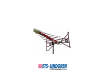
Model 3149 BiConiLog™ Antenna User Manual
ETS-Lindgren L.P. reserves the right to make changes to any product described herein in order to improve function, design, or for any other reason. Nothing contained herein shall constitute ETS-Lindgren L.P. assuming any liability whatsoever arising out of the application or use of any product or circuit described herein. ETS-Lindgren L.P. does not convey any license under its patent rights or the rights of others. © Copyright 2003–2009 by ETS-Lindgren L.P. All Rights Reserved.
Table of Contents Notes, Cautions, and Warnings ................................................ v 1.0 Introduction .......................................................................... 7 Standard Configuration .................................................................................. 8 Tripod Options ............................................................................................... 9 ETS-Lindgren Product Information Bulletin .................................................
This page intentionally left blank.
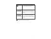
Notes, Cautions, and Warnings Note: Denotes helpful information intended to provide tips for better use of the product. Caution: Denotes a hazard. Failure to follow instructions could result in minor personal injury and/or property damage. Included text gives proper procedures. Warning: Denotes a hazard. Failure to follow instructions could result in SEVERE personal injury and/or property damage. Included text gives proper procedures.
This page intentionally left blank.
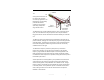
1.0 Introduction The ETS-Lindgren Model 3149 BiConiLog™ is a dual-purpose antenna that can be used for both emissions and immunity applications. The Model 3149 is a hybrid linearly polarized EMC antenna consisting of a log periodic dipole array (LPDA) and a single bow tie antenna. The Model 3149 has an ultra broadband frequency range, accepts high power input, and is size-efficient for easy transport and use in compact chambers.
An antenna constructed to maximize structural integrity is better able to maintain its electrical properties; the benefits are better measurement repeatability, lower uncertainty values, and longer calibration validity. The Model 3149 is able to thrive in an environment of constant use due to its rugged construction and the implementation of these design elements: • • Custom aluminum extrusions are used for the boom material.
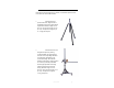
Tripod Options ETS-Lindgren offers the following non-metallic, non-reflective tripods for use at both indoor and outdoor EMC test sites. • 4-TR Tripod—Constructed of linen phenolic and delrin, designed with an adjustable center post for precise height adjustments. Maximum height is 2.0 m (80.0 in), and minimum height is 94 cm (37.0 in). This tripod can support up to an 11.8 kg (26.0 lb) load.
ETS-Lindgren Product Information Bulletin See the ETS-Lindgren Product Information Bulletin included with your shipment for the following: 10 • Warranty information • Safety, regulatory, and other product marking information • Steps to receive your shipment • Steps to return a component for service • ETS-Lindgren calibration service • ETS-Lindgren contact information | Introduction
2.0 Maintenance Before performing any maintenance, follow the safety information in the ETS-Lindgren Product Information Bulletin included with your shipment. Maintenance of the Model 3149 is limited to WARRANTY external components such as cables or connectors. If you have any questions concerning maintenance, contact ETS-Lindgren Customer Service. Annual Calibration See the Product Information Bulletin included with your shipment for information on ETS-Lindgren calibration services.
This page intentionally left blank.
3.0 Specifications Electrical Specifications Frequency Range: 80 MHz–5 GHz Impedance (Nominal): 50 Ω VSWR (Average): 6.5:1 (maximum)* <2:1 (typical) Maximum Continuous Power: • 800 W: 80 MHz–150 MHz • 500 W: 150 MHz–600 MHz • 360 W: 600 MHz–1 GHz • 200 W: 1 GHz–5 GHz Type N Connector: * 7:1 max is for bow tie element; better than 2:1 is for LPDA section Physical Specifications Height: 53.24 cm (20.96 in) Depth: 129.50 cm (50.98 in) Width: 91.00 cm (35.83 in) Weight: 5.0 kg (11.
This page intentionally left blank.
4.0 Bow Tie Assembly Instructions Before connecting any components, follow the safety information in the ETS-Lindgren Product Information Bulletin included with your shipment. The Model 3149 ships with the bow tie elements detached. The tubular bow tie elements easily attach to the balun box using positive aligning compression fittings. To attach the bow tie elements: 1. For stability, first mount the Model 3149 onto a tripod or tower.
Do not cross thread this connection or permanent damage to the bow tie element could occur. 16 3. Thread the compression fittings together using the included wrench. 4. Repeat steps 2 and 3 for the second bow tie element.
5.0 Mounting Instructions Before connecting any components, follow the safety information in the ETS-Lindgren Product Information Bulletin included with your shipment. The Model 3149 is a precision measurement device. Handle with care.
1. Located on the bottom of the polarizing adapter is a 7/8–14 thread receptacle; if you need to convert to a 1/4–20 receptacle, insert the 1/4–20 thread insert into the polarizing adapter. 2. Attach the polarizing adapter to tripod or tower. Do not cross thread or permanent damage to the adapter and thread insert could occur. 3. Remove the mounting knob from the mounting bracket on the antenna. 4.
Using the Stinger Mount The stinger mount provides on-axis rotation during 90° horizontal or vertical polarization. The stinger enables you to mount the antenna directly to an ETS-Lindgren 7-TR Tripod or mast. If mounting the Model 3149 to a 7-TR, use the center rotate boom (part# 108197) for rear-mount stinger-type antennas. Additional hardware is required to use the stinger to mount the Model 3149 to a mast.
Additional Mounting Options 4-TR MOUNTING OPTIONS Following are additional options for mounting the Model 3149 onto an ETS-Lindgren 4-TR tripod. Contact the ETS-Lindgren Sales Department for information on ordering optional mounting hardware.
7-TR AND MAST MOUNTING OPTIONS The stinger on the Model 3149 enables you to mount to antenna directly to an ETS-Lindgren 7-TR Tripod Positioner. Following are additional options for mounting the Model 3149 onto an ETS-Lindgren 7-TR Tripod Positioner. Contact the ETS-Lindgren Sales Department for information on ordering optional mounting hardware. Mast refers to 2070 Series, 2075, and 2175 Antenna Towers.
2X2 BOOM MOUNTING OPTIONS Following are additional options for mounting the Model 3149 onto a 2x2 boom. Contact the ETS-Lindgren Sales Department for information on ordering optional mounting hardware. 2x2 boom refers to a typical 2-inch by 2-inch boom.
OTHER MOUNTING OPTIONS Following are additional options for using the stinger to mount the Model 3149 onto a non-stinger mount. Contact the ETS-Lindgren Sales Department for information on ordering optional mounting hardware.
This page intentionally left blank.
6.
This page intentionally left blank.
7.
Model 3149 Gain at 10m 28 | Typical Data
Model 3149 Forward Power Typical Data | 29
Model 3149 Horizontal Measured Power Power requirements scaled from measured data for 3 V/m at 80% modulation over ferrite up to 1 GHz and measured over EHP-18PCL from 1 GHz to 2 GHz (horizontal polarization). Reference point: 3 m from antenna tip and 1.2 m over ground.
Model 3149 Vertical Measured Power Power requirements scaled from measured data for 3 V/m at 80% modulation over ferrite up to 1 GHz and measured over EHP-18PCL from 1 GHz to 2 GHz (vertical polarization). Reference point: 3 m from antenna tip and 1.2 m over ground.
This page intentionally left blank.
Appendix A: Warranty See the Product Information Bulletin included with your shipment for the complete ETS-Lindgren warranty for your Model 3149. DURATION OF WARRANTIES FOR MODEL 3149 All product warranties, except the warranty of title, and all remedies for warranty failures are limited to two years.