Model 3148B Log Periodic Dipole Array Antenna User Manual
ETS-Lindgren L.P. reserves the right to make changes to any product described herein in order to improve function, design, or for any other reason. Nothing contained herein shall constitute ETS-Lindgren L.P. assuming any liability whatsoever arising out of the application or use of any product or circuit described herein. ETS-Lindgren L.P. does not convey any license under its patent rights or the rights of others. © Copyright 1999–2008 by ETS-Lindgren L.P. All Rights Reserved.
Table of Contents Notes, Cautions, and Warnings ................................................... v 1.0 Introduction ............................................................................ 7 Tripod Options ...............................................................................................8 ETS-Lindgren Product Information Bulletin ...................................................9 2.0 Maintenance ........................................................................
1100 MHz ....................................................................................................35 1200 MHz ....................................................................................................35 1300 MHz ....................................................................................................36 1400 MHz ....................................................................................................36 1500 MHz .......................................................
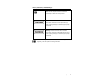
Notes, Cautions, and Warnings Note: Denotes helpful information intended to provide tips for better use of the product. Caution: Denotes a hazard. Failure to follow instructions could result in minor personal injury and/or property damage. Included text gives proper procedures. Warning: Denotes a hazard. Failure to follow instructions could result in SEVERE personal injury and/or property damage. Included text gives proper procedures.
This page intentionally left blank.
1.0 Introduction The ETS-Lindgren Model 3148B Log Periodic Dipole Array is a linearly-polarized broadband antenna designed to operate over the frequency range of 200 MHz to 2 GHz. The choice of scaling factors, the various diameters of each element, and the center-to-center spacing of the booms yield excellent VSWR characteristics throughout the operating frequency range (see VSWR on page 29).
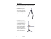
Tripod Options ETS-Lindgren offers the following nonmetallic, non-reflective tripods for use at both indoor and outdoor EMC test sites. • Model 4-TR—Constructed of linen phenolic and delrin, designed with an adjustable center post for precise height adjustments. Maximum height is 2.0 m (80.0 in), and minimum height is 94 cm (37.0 in). This tripod can support up to an 11.8 kg (26.0 lb) load.
ETS-Lindgren Product Information Bulletin See the ETS-Lindgren Product Information Bulletin included with your shipment for the following: • Warranty information • Safety, regulatory, and other product marking information • Steps to receive your shipment • Steps to return a component for service • ETS-Lindgren calibration service • ETS-Lindgren contact information Introduction | 9
This page intentionally left blank.
2.0 Maintenance Before performing any maintenance, follow the safety information in the ETS-Lindgren Product Information Bulletin included with your shipment. WARRANTY Maintenance of the Model 3148B is limited to external components such as cables or connectors. If you have any questions concerning maintenance, contact ETS-Lindgren Customer Service. Annual Calibration See the Product Information Bulletin included with your shipment for information on ETS-Lindgren calibration services.
Part Description Part Number Antenna Element, .250, 8.58inches 105568-7 Antenna Element, .250, 9.8 inches 105568-8 Antenna Element, .250, 11.18 inches 105568-9 Antenna Element, .250, 12.62 inches 105568-10 Antenna Element, .187, .99 inches 105569-1 Antenna Element, .187, 1.17 inches 105569-2 Antenna Element, .187, 1.37 inches 105569-3 Antenna Element, .187, 1.6 inches 105569-4 Antenna Element, .187, 1.86 inches 105569-5 Antenna Element, .187, 2.16 inches 105569-6 Antenna Element, .
3.0 Specifications Electrical Specifications Frequency Range: 200 MHz–2 GHz VSWR Ratio: Average: 1.2:1 Maximum: 2.0:1 Maximum Continuous Power: 1 kW Peak Power: 1.3 kW Impedance: 50 Ω Symmetry: ± 0.5 dB Cross-Polarization Rejection: Better than 20 dB below 1000 MHz Connector: Type N female Physical Specifications Height (without bracket assembly): 6.667 cm 2.625 in Width (at widest point): 85.09 cm 33.50 in Length 86.677 cm (including stinger): 34.125 in Weight: 2.0 kg 4.
This page intentionally left blank.
4.0 Mounting Instructions Before connecting any components, follow the safety information in the ETS-Lindgren Product Information Bulletin included with your shipment. Using Included Mounting Adapters The Model 3148B Log Periodic Dipole Array ships with these mounting adapters: • 100989 Polarizing Mounting Adapter with 7/8–14 thread receptacle • 105861B 1/4–20 Thread Insert To use these adapters to mount the Model 3148B to a tripod or tower: 1.
Do not cross thread or permanent damage to the adapter and thread insert could occur. 3. Remove the mounting knob from the mounting bracket on the antenna. 4. Slide the mounting bracket onto the polarizing adapter with the polarizing adapter placed between the shoulders of the mounting bracket. 5. Thread the mounting knob through the mounting bracket, then through the polarizing adapter, and finally through the hex nut. 6. 16 Tighten the mounting knob to secure the antenna.
Shown mounted onto a 4-TR Mounting Instructions | 17
Using the Stinger Mount The stinger on the Model 3148B enables you to mount to antenna directly to an ETS-Lindgren 7-TR Tripod Positioner or mast. Additional hardware is required to use the stinger to mount the Model 3148B to a mast. For information on ordering optional mounting hardware, contact the ETS-Lindgren Sales Department. Do not use the stinger to mount the Model 3148B onto a 4-TR tripod.
Additional Mounting Options 4-TR MOUNTING OPTIONS Following are additional options for mounting the Model 3148B onto an ETS-Lindgren 4-TR tripod. Contact the ETS-Lindgren Sales Department for information on ordering optional mounting hardware.
7-TR AND MAST MOUNTING OPTIONS The stinger on the Model 3148B enables you to mount to antenna directly to an ETS-Lindgren 7-TR Tripod Positioner. Following are additional options for mounting the Model 3148B onto an ETS-Lindgren 7-TR Tripod Positioner. Contact the ETS-Lindgren Sales Department for information on ordering optional mounting hardware. Mast refers to 2070 Series, 2075, and 2175 Antenna Towers.
2X2 BOOM MOUNTING OPTIONS Following are additional options for mounting the Model 3148B onto a 2x2 boom. Contact the ETS-Lindgren Sales Department for information on ordering optional mounting hardware. 2x2 boom refers to a typical 2-inch by 2-inch boom.
This page intentionally left blank.
5.0 Application Emissions and Immunity The antenna label on the Model 3148B Log Periodic Dipole Array marks the centerline and tip of the antenna, indicating where to perform measurements.
Operation After mounting the Model 3148B onto an ETS-Lindgren tripod or antenna mast adapter, connect an N-type coaxial cable from the antenna connector to a generator (immunity) or receiver (emissions). Both horizontal and vertical polarizations are easily accomplished when the Model 3148B is mounted onto a tower or tripod. Contact with any metallic or non-metallic structure can capacitively load the antenna, which may cause inconsistent results.
For IEC/EN 31000-4-3 type testing, the antenna tip can be placed at any distance between one and three meters from the EUT as long as the front face plane is illuminated according to the -0, +6 dB uniform field specifications. It is usually necessary to place RF absorbing material between the EUT and antenna to suppress ground plane reflection to ensure the field uniformly, or to conduct the immunity test in a fully-lined anechoic room.
This page intentionally left blank.
6.
Gain 28 | Typical Data
VSWR Typical Data | 29
Half-Power Beamwidth 30 | Typical Data
7.
500 MHz 600 MHz 32 | Typical Radiation Patterns
700 MHz 800 MHz Typical Radiation Patterns | 33
900 MHz 1000 MHz 34 | Typical Radiation Patterns
1100 MHz 1200 MHz Typical Radiation Patterns | 35
1300 MHz 1400 MHz 36 | Typical Radiation Patterns
1500 MHz 1600 MHz Typical Radiation Patterns | 37
1700 MHz 1800 MHz 38 | Typical Radiation Patterns
1900 MHz 2000 MHz Typical Radiation Patterns | 39
This page intentionally left blank.
Appendix A: Warranty See the Product Information Bulletin included with your shipment for the complete ETS-Lindgren warranty for your Model 3148B Log Periodic Dipole Array. DURATION OF WARRANTIES FOR MODEL 3148B All product warranties, except the warranty of title, and all remedies for warranty failures are limited to two years.