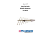
Model 3147 Log Periodic Dipole Antenna User Manual
ETS-Lindgren L.P. reserves the right to make changes to any product described herein in order to improve function, design, or for any other reason. Nothing contained herein shall constitute ETS-Lindgren L.P. assuming any liability whatsoever arising out of the application or use of any product or circuit described herein. ETS-Lindgren L.P. does not convey any license under its patent rights or the rights of others. © Copyright 1999–2010 by ETS-Lindgren L.P. All Rights Reserved.
Table of Contents Notes, Cautions, and Warnings ................................................ v 1.0 Introduction .......................................................................... 7 Regarding Calibration of Log Periodic Dipole Antennas................................ 8 ETS-Lindgren Product Information Bulletin ................................................... 9 2.0 Maintenance ....................................................................... 11 Maintenance Recommendations ..............
80 Watts Continuous Power ........................................................................ 36 40 Watts Continuous Power ........................................................................ 38 Appendix A: Typical Antenna Patterns ................................. 41 400 MHz ...................................................................................................... 41 500 MHz ......................................................................................................
Notes, Cautions, and Warnings Note: Denotes helpful information intended to provide tips for better use of the product. Caution: Denotes a hazard. Failure to follow instructions could result in minor personal injury and/or property damage. Included text gives proper procedures. Warning: Denotes a hazard. Failure to follow instructions could result in SEVERE personal injury and/or property damage. Included text gives proper procedures.
This page intentionally left blank.
1.0 Introduction The ETS-Lindgren Model 3147 Log Periodic Dipole Antenna is a linearly-polarized broadband antenna designed to operate over the frequency range of 200 MHz to 5 GHz. The antenna was designed with the latest revision to Part 15 of FCC Rules and Regulations in mind. See page 13 for specifications. The Model 3147 is constructed from 30 elements mounted on two 6.35-mm by 12.7-mm booms.
Because the radome is almost RF-invisible, it has very little effect on the performance of the Model 3147 (see VSWR on page 23). The base of the Model 3147 accepts an ETS-Lindgren or other tripod mount with 1/4–20 threads. Additionally, the antenna is shipped with a support rod. A variety of mounting options are available for the Model 3147. For information, see Mounting Instructions on page 15.
ETS-Lindgren Product Information Bulletin See the ETS-Lindgren Product Information Bulletin included with your shipment for the following: • Warranty information • Safety, regulatory, and other product marking information • Steps to receive your shipment • Steps to return a component for service • ETS-Lindgren calibration service • ETS-Lindgren contact information Introduction | 9
This page intentionally left blank.
2.0 Maintenance Before performing any maintenance, follow the safety information in the ETS-Lindgren Product Information Bulletin included with your shipment. Maintenance of the Model 3147 Log Periodic Dipole Antenna is limited to external components such as cables or connectors. If you have any questions concerning maintenance, contact ETS-Lindgren Customer Service.
This page intentionally left blank.
3.0 Specifications Electrical Specifications Frequency Range: 200 MHz–5 GHz VSWR: Average: 1.25:1 Maximum: 1.7:1 Impedance: 50 Ω Maximum Continuous 80 W at 1 GHz Input Power: 40 W at 5 GHz Maximum Peak Input Power: 100 W at 1 GHz 50 W at 5 GHz Precision N female Connector: Physical Specifications Height: 7.62 cm 3.0 in Width: 88 cm 34.65 in Depth: 97 cm 38.19 in Weight: 4.25 kg 9.
This page intentionally left blank.
4.0 Mounting Instructions Before connecting any components, follow the safety information in the ETS-Lindgren Product Information Bulletin included with your shipment. The Model 3147 is a precision measurement device. Handle with care.
To attach the included adapters to the Model 3147: 1. If required, insert the 1/4–20 thread insert into the polarizing adapter. 2. Remove the mounting knob from the mounting bracket on the antenna. 3. Slide the polarizing adapter into the mounting bracket by placing the polarizing adapter placed between the shoulders of the mounting bracket.
4. Thread the mounting knob through the mounting bracket, then through the polarizing adapter, and finally through the hex nut. Do not cross thread or permanent damage to the adapter could occur. 5. Tighten the mounting knob to secure the antenna. 6. Attach the polarizing adapter and antenna to tripod or tower, as required. Additional Mounting Options 4-TR MOUNTING OPTIONS Following are additional options for mounting the Model 3147 onto an ETS-Lindgren 4-TR tripod.
7-TR AND MAST MOUNTING OPTIONS Following are options for mounting the Model 3147 onto an ETS-Lindgren 7-TR Tripod or mast. Contact the ETS-Lindgren Sales Department for information on ordering optional mounting hardware. Mast refers to 2070 Series, 2075, and 2175 Antenna Towers.
2X2 BOOM MOUNTING OPTIONS Following are additional options for mounting the Model 3147 onto a 2x2 boom. Contact the ETS-Lindgren Sales Department for information on ordering optional mounting hardware. 2x2 boom refers to a typical 2-inch by 2-inch boom.
This page intentionally left blank.
5.0 Operation Before connecting any components, follow the safety information in the ETS-Lindgren Product Information Bulletin included with your shipment. Model 3147 Assembly Instructions A variety of mounting options are available for the Model 3147. For information, see Mounting Instructions on page 15. To attach the support rod to the base of the Model 3147 Log Periodic Dipole Antenna: 1. Remove the clamping screw from the mount on the antenna. 2. Insert the support rod. 3. Replace the screw. 4.
This page intentionally left blank.
6.0 Typical Data Following are typical measurements for the Model 3147 Log Periodic Dipole Antenna. Typical VSWR for Model 3147 This is a plot of the VSWR showing the antenna with and without a radome. The effect of the radome on the electromagnetic performance of the antenna is minimal.
Typical Antenna Factor and Gain for Model 3147 24 | Typical Data
The antenna factor of the Model 3147 (triangles) measured at the distance of three meters as per ANSI C63.5. The standard states that the spacing R between log-periodic array antennas is measured from the projection onto the ground plane of the midpoint of the longitudinal axis of each antenna. This midpoint has been marked on the radome and labeled Reference Point Per ANSI C63.5. The line shown in the figure is a linear fit to the antenna factor data.
Beamwidth for Horizontally and Vertically Polarized Model 3147 The beamwidth charts show the 3-dB and 10-dB power beamwidth as determined from the antenna patterns taken for both horizontal and vertical polarizations.
Typical Data | 27
Front-to-Back Ratio for Model 3147 The front-to-back ratio is representative of how well the antenna propagates energy in the end fire direction. The measurement is made by first positioning two identical Model 3147 antennas face-to-face at a 2-meter height and a 3-meter distance. A signal is transmitted through one antenna and received with the other. The transmitting antenna is then rotated 180° in azimuth so that the back is pointed towards the receiving antenna.
Cable Attenuation (dB) at 20°C for 6-M Cable Typical Data | 29
Typical Antenna Pattern for 200 MHz and 300 MHz This shows a sample antenna pattern taken at selected frequencies of 200 MHz and 300 MHz. Additional antenna patterns are located in Appendix A on page 41. These patterns were measured indoors using a separation distance of 1 meter to 1.5 meters between the transmit antenna and the receive antenna.
7.0 Radiated Emissions Measurement Before connecting any components, follow the safety information in the ETS-Lindgren Product Information Bulletin included with your shipment. Ambient field strength values are measured as follows: 1. Install the antenna where measured field strength values are desired. 2. Select the desired orientation of the antenna, both boresite direction and polarization. 3. Connect the antenna output connector to the input of the receiving system using a coaxial cable.
If a long coaxial cable is used between the antenna and the receiving device, or the frequency of the observation is more than several tens of MHz, the losses in the coaxial cable, Ae, must be included in the computation. In this case the computation is: -1 RF Voltage, dB(µV) + Cable Loss, dB + Antenna Factor, dB (m ) = Field Strength dB (µV/m) Ea = Va + AF + Ae Conversion Factors Following are some useful conversion formulas. dBm = dB(µV) – 107 dB(mW/m2) = dB(µV/m) – 115.
In a 50-Ω system, the above equation becomes: 10 log10P = 20 log10 V – 10 log10(50) Converting from dB to dBm for power and from dB(V) to dB(µV) for voltage, the added constant becomes: 30 – 120 – 10 log10(50) = –107 The constant in the second equation is obtained by considering the pointing 2 vector which relates the power density in (W/m ) to the electric field density in (V/m) by: |E|2 P= η Where η is the free space characteristic impedance equal to 120π Ω.
This page intentionally left blank.
8.0 Power Requirements The Model 3147 Log Periodic Dipole Antenna may also be used as a transmitting antenna. The power input requirements for a desired electric field strength level are provided in the Power Requirements table on page 36. The power is computed according to the transmission equation: 2 (field strength) (distance in meters) Power transmitted = 2 (30 x Numeric Gain) 2 2 |E| R Pt = 30 g In the Power Requirements table on page 36, R is 3 meters.
Power Requirements Table Power requirements for a given field strength computed using typical antenna calibration factors at 3-meter spacing. 80 WATTS CONTINUOUS POWER Field Strength (E) Freq Gain Gain (dB) (num) AF (MHz) 36 1 V/m 10 V/m 20 V/m 200 11.7 4.5 2.8 0.106 10.6 42.6 225 12.8 4.5 2.8 0.106 10.6 42.6 250 12.9 5.2 3.3 0.091 9.1 36.2 275 13.5 5.5 3.5 0.085 8.5 33.8 300 13.8 6.0 4.0 0.075 7.5 30.1 325 14.1 6.3 4.3 0.070 7.0 28.1 350 14.9 6.2 4.
Field Strength (E) Freq Gain Gain (dB) (num) AF (MHz) 1 V/m 10 V/m 20 V/m 625 19.6 6.5 4.5 0.067 6.7 26.9 650 20.2 6.3 4.3 0.070 7.0 28.1 675 20.3 6.5 4.5 0.067 6.7 26.9 700 21.2 5.9 3.9 0.077 7.7 30.8 725 21.6 5.9 3.9 0.077 7.7 30.8 750 21.9 5.8 3.8 0.079 7.9 31.6 775 21.4 6.6 4.6 0.066 6.6 26.3 800 21.1 7.2 5.2 0.057 5.7 22.9 825 21.6 6.9 4.9 0.061 6.1 24.5 850 22.1 6.7 4.7 0.064 6.4 25.6 875 22.8 6.3 4.3 0.070 7.0 28.
40 WATTS CONTINUOUS POWER Field Strength (E) Freq Gain Gain (dB) (num) AF (MHz) 38 1 V/m 10 V/m 20 V/m 1000 23.2 7.0 5.0 0.060 6.0 23.9 1100 23.4 7.6 5.8 0.052 5.2 20.8 1200 23.8 8.1 6.5 0.046 4.6 18.6 1300 24.1 8.4 6.9 0.043 4.3 17.3 1400 25.6 7.5 5.6 0.053 5.3 21.3 1500 26.2 7.6 5.8 0.052 5.2 20.8 1600 26.7 7.6 5.8 0.052 5.2 20.8 1700 27.6 7.3 5.4 0.056 5.6 22.3 1800 28.5 6.9 4.9 0.061 6.1 24.5 1900 28.5 7.3 5.4 0.056 5.6 22.
Field Strength (E) Freq Gain Gain (dB) (num) AF (MHz) 1 V/m 10 V/m 20 V/m 3000 34.0 5.8 3.8 0.079 7.9 31.6 3100 35.1 5.0 3.2 0.095 9.5 37.9 3200 34.6 5.7 3.7 0.081 8.1 32.3 3300 34.9 5.7 3.7 0.081 8.1 32.3 3400 35.5 5.3 3.4 0.089 8.8 35.4 3500 36.8 4.3 2.7 0.111 11.1 44.6 3600 36.9 4.4 2.8 0.109 10.9 43.6 3700 36.6 5.0 3.2 0.095 9.5 37.9 3800 35.8 6.0 4.0 0.075 7.5 30.1 3900 36.9 5.2 3.3 0.091 9.1 36.2 4000 37.6 4.7 3.0 0.
This page intentionally left blank.
Appendix A: Typical Antenna Patterns 400 MHZ 500 MHZ Typical Antenna Patterns | 41
600 MHZ 700 MHZ 42 | Typical Antenna Patterns
800 MHZ 900 MHZ Typical Antenna Patterns | 43
1.0 GHZ 1.
2.0 GHZ 2.
3.0 GHZ 3.
4.0 GHZ 4.
5.
Appendix B: Warranty See the Product Information Bulletin included with your shipment for the complete ETS-Lindgren warranty for your Model 3147 Log Periodic Dipole Antenna. DURATION OF WARRANTIES FOR MODEL 3147 All product warranties, except the warranty of title, and all remedies for warranty failures are limited to two years.