Archived 3/18/10 USER MANUAL EMCO MODEL 3141 BICONILOGTM LOG-PERIODIC / T BOW-TIE ANTENNA 399236 Rev A 01/97
Archived 3/18/10 GENERAL DESCRIPTION The EMCO Model 3141 is the latest evolution in the popular bow-tie/log periodic combination BiConiLogTM family. A biconilog antenna combines a broadband biconicallike bow-tie antenna with a standard log periodic to replace the traditional use of two antennas in the 30-1000 MHz EMC test frequencies. Many EMC antennas are variations of a standard tuned dipole.
Archived 3/18/10 0.5 dB), in vertically polarized measurements cable position can effect results, so it is recommended that the cable be suspended horizontally back from the antenna at least 1 meter before any vertical drop. Below 150 MHz, bow-tie radiation dominates with a dipole-like pattern, while above 150 MHz the radiation in the plane of the elements is directional. The antenna has a mounting bracket and 1/4x20 UNC knob for attaching to EMCO tripod and tower adaptors.
Archived 3/18/10 APPLICATION Install the Model 3141 without the T bow-ties on an EMCO tripod or tower adaptor. Insert the bow-ties one at a time and tighten the base knobs. Attach each T end frame with four knobs. Connect an N-type coaxial cable from the antenna connector to a generator or receiver. Contact with any metal or non-metallic structure can capacitively load the antenna which may cause unrepeatable results.
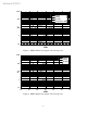
Archived 3/18/10 by the formula E ( V / m) = 30 Pg , d where d is in meters, g is the numeric gain (10G[dB]/10, see attached calibration data), and P is antenna net input power in watts. An estimate of the power required for any field strength E can be obtained from Figure 3 or 4 in the Typical Data section below, which shows power required in watts to generate 1 V/m. For any other field strength not shown, multiply the power in watts by the desired E-field squared, or P( E V / m) = E 2 P(1 V / m) .
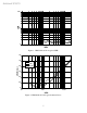
Archived 3/18/10 TYPICAL DATA Figure 1 shows typical 26-2000 MHz VSWR for the EMCO Model 3141. Figure 2 shows typical 3141 26-2000 MHz antenna factors. Distance for the ANSI 3 and 10 meter calibrations is measured from the antenna midpoint, while for SAE 1 meter calibrations the distance is measured from the antenna tip. Midpoint is defined as half the distance between the small elements and the bow-ties, which is about 45 cm from the small end tip.
Archived 3/18/10 SWR 100 10 1 10 100 1000 MHz Figure 1. EMCO Model 3141 typical SWR. 35 AF dB[1/m] 30 1m 3m 10 m 25 20 15 10 5 10 100 1000 MHz Figure 2. EMCO Model 3141 typical antenna factor.
Archived 3/18/10 1000 1 V/m 3 V/m 10 V/m 3 V/m 80% AM W 100 10 1 0.1 20 30 40 50 60 70 80 MHz Figure 3. EMCO Model 3141 typical 1 m forward power. 1000 1 V/m 3 V/m 10 V/m W 100 10 1 0.1 20 30 40 50 60 70 MHz Figure 4. EMCO Model 3141 typical 3 m forward power.
Archived 3/18/10 SPECIFICATIONS Electrical (nominal): Frequency range 26 - 2000 MHz Input impedance 50 Ω VSWR 2:1 average CW power 1 kW, above 60 MHz 500 W, below 60 MHz Symmetry +/- 0.5 dB Connector N female Mechanical: Height (T bow-tie) 75 cm Width (T bow-tie) 136 cm Depth (length) 132 cm Weight 6.
Archived 3/18/10 WARRANTY EMC Test Systems warrants that our products are free from defects in materials and workmanship for a period of two years from the date of shipment. If you notify us of a defect within the warranty period, we will, at our option, either repair or replace those products which prove to be defective. If applicable, we will also recalibrate the product. There will be no charge for warranty services at the location we designate.