Turntable Model 2188 1.2m, 1.5m and 2.0m Users Manual ©ETS-Lindgren—January, 2006 Rev.
Model 2188 Turntable ETS-Lindgren reserves the right to make changes to any products herein to improve functioning or design. Although the information in this document has been carefully reviewed and is believed to be reliable, ETS-Lindgren does not assume any liability arising out of the application or use of any product or circuit described herein; nor does it convey any license under its patent rights nor the rights of others. ©Copyright 2006 by ETS-Lindgren L.P. All Rights Reserved.
Model 2188 Turntable Table of Contents 1. Introduction .................................................................................................................................. 7 1.1. Standard Configuration ......................................................................................................... 7 1.2. Model 2188 Options.............................................................................................................. 8 1.2.1. Model 2090 Series Positioning Controller ...
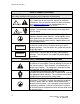
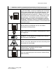
Model 2188 Turntable SAFETY SYMBOL DEFINITIONS NOTICE: This product and related documentation must be reviewed for familiarization with safety markings and instructions prior to operation of the product. REFER TO MANUAL—When the product is marked with this symbol refer to the instruction manual for additional information. If the instruction manual has been misplaced, go to www.ets-lindgren.com for downloadable files or OR contact ETS-Lindgren customer service.
Model 2188 Turntable GENERAL SAFETY CONSIDERATIONS/PRECAUTIONS (continued) WARRANTY BEFORE SERVICING: CONTACT ETS-LINDGREN (+1.512.531.6400)—servicing or modifying the unit without ETS-Lindgren authorization may void your warranty. If an attempt to service the unit must be made, disconnect all electrical power prior to beginning. Voltages exist at many points within the instrument that could, if contacted, cause personal injury.
Model 2188 Turntable This page intentionally left blank. 6 ©ETS-Lindgren—January, 2006 Rev.
Model 2188 Turntable 1. Introduction The ETS-Lindgren Model 2188 is an electric-powered, variable-speed turntable platform system designed for use with an EMCO Model 2090 series positioning controller to perform EMI compliance testing. The Model 2188 is available in 1.2-meter, 1.5-meter and 2.0-meter diameters. The turntable is ideal for installations in new or existing test locations where pit excavation is not an option or must be shallow.
Model 2188 Turntable 1.2. Model 2188 Options 1.2.1. Model 2090 Series Positioning Controller The Model 2090 Series Multi-Device Positioning Controller is designed for use with ETS-Lindgren positioning devices such as antenna towers, turntables, reverberation paddles, multi-axis positioners, etc. to accomplish a variety of tests for EMC compliance, antenna pattern measurements, and more.
Model 2188 Turntable Control of all devices may be accomplished either in the manual or remote modes through the use of the GPIB (IEEE 488 standard interface bus) port located on the rear panel. Each primary device is identified by a unique GPIB address that the controller recognizes, allowing each positioning device to function as a separate device on the GPIB bus. 1.2.2. Additional Fiber Optic Cable Various lengths of fiber optic cable may be ordered.
Model 2188 Turntable This page intentionally left blank. 10 ©ETS-Lindgren—January, 2006 Rev.
Model 2188 Turntable 2. Getting Started 2.1. Unpacking and Acceptance Step 1. Upon delivery of your order, inspect the shipping container(s) for evidence of damage. Record any damage on the delivery receipt before signing. In case of concealed damage or loss, retain the packing materials for inspection by the carrier. Step 2.
Model 2188 Turntable 2.2.1. Mechanical Diameter 1.2 meter 1.5 meter 2.0 meter Height 16.51 cm 16.51 cm 16.51 cm (Minimum) (6.12 in.) (6.12 in.) (6.12 in.) Distributed 500 kg 1,000 kg 1,000 kg Load (1,100 lb) (2,200 lb) (2,200 lb) Rating* *Distributed Load Rating is based on an evenly distributed load to each section. Point loads under 0.37 sq. m (4 sq. ft) should not exceed 500 kg (1,100 lb.). Nothing over 400 kg (882 lb.) may be applied to a 45-degree segment outboard of the casters.
Model 2188 Turntable 3. Installation The turntable installation will vary based on the host location. Several installation options may be presented in the steps that follow. Please select the option that applies to your location. The installation of turntables must be performed by a factory installation specialist or by individuals who have been authorized by ETS-Lindgren to do such work. Proper installation of the turntable directly affects performance.
Model 2188 Turntable 3.2. Unpacking A qualified installer will perform the following steps in preparation for installation of the turntable. Please pull the drawings from the back pocket of this manual to assist in the installation directions that follow. 1. Uncrate all parts. Check all parts for any shipping damage. Ensure a clear area is available to assemble the turntable unit safely. NOTE: Do not discard any packing material or parts until the turntable is fully assembled. 2.
Model 2188 Turntable Figure 1: Turntable Interior Design Figure 2: Turntable Pit Locator Detail ©ETS-Lindgren—January, 2006 Rev.
Model 2188 Turntable 6. Position the table as close as possible to the center. Attach the measuring bar provided to the brass spacers mounted onto the bearing. Note the appropriate hole-mount locations in reference to the size of the turntable to be installed. Rotate the bearing and ensure approximately 7/8” to 1” spacing exists between the edge of the outer measuring bar and the diameter of hole cut into the pit. Adjust if necessary. 7.
Model 2188 Turntable 12. When mounting to a steel pit and steel raised floor, a #7 drill bit for tapping or a 9/32 drill bit to create “through holes” is required when mounting anchor plates to the steel raised floor. Locate and mark holes in each group of anchor plates. Drill and tap or drill through each hole and then screw in ¼-20 hardware so that the table does not move as you go around each location. Proceed with leveling instructions.
Model 2188 Turntable Mounting methods vary according to user specifications. Clearance holes are provided, at evenly spaced intervals, along the outside perimeter of the ground ring as a means of attaching the ring to a customer supplied ground plane. These instructions cover installation for a paneled floor; please see the section on “Floor Flange Mounting in Concrete Pit” for further instructions regarding mounting in a concrete pit. For this step you will need three ¼” spacers i.e.
Model 2188 Turntable Figure 4:Turntable Motorbase A ½” hammer drill, 3/16 x 3 ½” min. hammer drill bit, and a vacuum to clean in holes drilled for maximum thread engagement will be required for this stage of the installation. NOTE: When drilling holes, watch out for buried conduit and pit drainpipes. Drill 3/16” holes 2” min. depth. 3.7. Motorbase Attachment Locate the box that contains the motorbase. The box also includes the hardware needed to attach the motorbase to the turntable.
Model 2188 Turntable 3.8. Final Leveling of the Table Once the table is in place with the floor flange and wear strip mounted, check that the table is level. Ensure that it is level and all screws, nuts, and collars have been tightened. 3.9. Application of Conductive Grease Before placing the turntable into operation, apply conductive grease to the ground brush. Apply the contents of one tube of GC Electronics conductive grease to the brush. Apply one tube per meter size of the diameter of the table.
Model 2188 Turntable 4. Electrical Installation CAUTION: Electrical connection should only be performed by a qualified electrician and subject to local electrical codes. The Model 2188 is designed to operate using 208-230 VAC single-phase 50 or 60Hz power. The branch circuit supplying power to the motor base should be protected from excess current according to local electrical codes. ETS-Lindgren has provided integral circuit protection in the motor base assembly.
Model 2188 Turntable This page intentionally left blank. 22 ©ETS-Lindgren—January, 2006 Rev.
Model 2188 Turntable 5. Operation Please refer to the Model 2090 series positioning controller manual if you are unfamiliar with the operation of the unit. A manual is included with each positioning controller shipment and is also available for download from our website, www.ets-lindgren.com. With the assembly of the turntable complete the Model 2090 series controller must be connected to the unit and power applied to both the motor base and controller in order to continue.
Model 2188 Turntable 5.2. Setting Travel Limits Figure 5: Turntable Limit Switch The Model 2188 is fitted with mechanically actuated or “hard” limit switches. These switches are adjustable to allow for limited travel beyond zero and 360 degrees. Actuation pins are placed in the turntable top to engage the limit switch mechanism. The limit switch mechanism is designed so that the amount of travel is dictated by the pin position in the turntable top.
Model 2188 Turntable the ENTER key. To set the clockwise rotational limit for the turntable, press the UP/CW key under LIMIT. The indicator light above this key will light. Set the limit by pressing the INCRM and DECRM keys under LIMIT until the desired limit is shown on the display. Press the ENTER key. WARNING: Ensure the current travel limit settings will not cause damage to existing cables and equipment located underneath the turntable.
Model 2188 Turntable 5. Record the reading of the display, ignoring the decimal point (i.e. 360.0 would be 3600). This is the encoder calibration value. NOTE: If the value is below 3600, the resolution of the encoder is low and consequently the controller will not provide 0.1degree resolution, even though the display shows that digit. If the value has gone past 9999, the encoder has too many counts per meter and the controller cannot correct for it. In this case, contact ETS-Lindgren for assistance. 6.
Model 2188 Turntable • The table is rotated from 0 to 360 and the mark is now within one degree of being one full turntable revolution. Calibration is complete. 5.4. Changing Rotation Speed The Model 2188 turntable is equipped with a variable speed drive. Firmware Revision 3.11 (or higher) must be installed in the Model 2090 series controller for proper operation of the Model 2188. The revision level is displayed on the front panel LED display during startup of the Model 2090 series controller.
Model 2188 Turntable WARNING: Do not operate the turntable in a stalled condition. Doing so may cause damage to the drive unit and will nullify your warranty. Always insure that the minimum speed setting specified in the S1-S4 parameters is above the minimum value at which your table will turn under normal load. 5.6. Speed Selection For the Variable Speed Turntable, the Polarization/Flotation button provides the ability to cycle between the eight preset speeds described above.
Model 2188 Turntable 5.7. GPIB Commands The following GPIB commands have been added or modified: • • • • Sn: Select Speed, where n is 1 or 2 for a two-speed turntable and 1-4 for a variable speed turntable. S?: Query speed selection. Returns 1 or 2 for a two-speed turntable and 1-4 for a variable speed turntable. SSn: Set Speed Value, where “n” is 1-4. This command is valid only for a variable speed turntable. Valid speed values are from 1 to 255.
Model 2188 Turntable This page intentionally left blank. 30 ©ETS-Lindgren—January, 2006 Rev.
Model 2188 Turntable 6. Infrared Controller The motor base features an infrared receiver that will respond to a universal remote control programmed to a specific protocol. Any remote that continuously transmits and contains the proper TV protocol can be used.
Model 2188 Turntable This page intentionally left blank. 32 ©ETS-Lindgren—January, 2006 Rev.
Model 2188 Turntable 7. Recommended Maintenance CAUTION: Do not perform maintenance while turntable is operating. Disconnect the power connection for safety. Only qualified individuals should conduct these maintenance inspections. Regular maintenance will prolong the serviceable life of your turntable. Follow this recommended schedule. Use the inspection log that follows to maintain a record of maintenance described below. 7.1.
Model 2188 Turntable 7.3. Annual Maintenance These maintenance items should occur every twelve months after the turntable is put into service. • • 34 Lubricate the main bearing race. Use a grease gun with a good quality bearing grease. The grease fittings are located inside the race, 90 degrees apart, underneath the top. Three discharges from the grease gun in each fitting are adequate. Using synthetic grease, grease all casters. Mobil 1 synthetic is recommended; do not use lithium grease.
Model 2188 Turntable EMCO Model 2188 Turntable Maintenance Log Routine Bi-Annual Annual Routine Bi-Annual Routine Check Annual Routine Bi-Annual Annual Remove foreign objects between turntable top and floor flange Check for excessive rotation by hand Listen for excessive noise Bi-Annual Check Grease the casters Inspect the ground brush for contaminates Inspect the ground brush for wear, replace if necessary Annual Check Lubricate the main bearing race Lubricate chain and sprocket of the chain drive
EMCO Model 2188 Turntable This page intentionally left blank. 36 ©ETS-Lindgren—October, 2005 Rev.
8. Warranty SCOPE AND DURATION OF WARRANTIES Seller warrants to Buyer that the Standard EMCO Brand Products Excluding 5211 & 5220 be (1) free from defects in material, manufacturing workmanship, and title, and (2) conform to the Seller’s applicable product descriptions and specifications, if any, contained in or attached to Seller’s quotation.
Model 2188 Turntable BUYER’S REMEDIES If Seller determines that any product fails to meet any warranty during the applicable warranty period, Seller shall correct any such failure by either, at its option, repairing, adjusting, or replacing without charge to Buyer any defective or nonconforming product, or part or parts of the product. Seller shall have the option to furnish either new or exchange replacement parts or assemblies.
9. Addendum A: Drawings Please locate the drawings placed in pocket of the back cover of this manual. Drawings include ETS-Lindgren drawing numbers: • • • • • • • • 2188-1.23B 2188-1.53 rev. 2 2188-2.03 rev. 1 108912C 110053B 110277 rev. 2 110406 rev. 2 398790 ©ETS-Lindgren—January, 2006 Rev.