Model 2181 Electric-Powered Turntable 2-Meter, 3-Meter, 4-Meter, 5-Meter User Manual Model 2181 2.
ETS-Lindgren L.P. reserves the right to make changes to any products herein to improve functioning or design. Although the information in this document has been carefully reviewed and is believed to be reliable, ETS-Lindgren does not assume any liability arising out of the application or use of any product or circuit described herein; nor does it convey any license under its patent rights nor the rights of others. All trademarks are the property of their respective owners.
Table of Contents Notes, Cautions, and Warnings .........................................................................v 1.0 Introduction ...................................................................................................7 Model 2181 Standard Configuration................................................................................... 7 Turntable Assembly............................................................................................... 7 Shield Room Feed-through ...........
5.0 Electrical Installation ..................................................................................17 Model 2181 Electrical Installation ..................................................................................... 17 Connecting the Model 2090 Controller............................................................................. 18 6.0 Assembly and Installation..........................................................................19 Assembly Instructions..............................
Notes, Cautions, and Warnings Note: Denotes helpful information intended to provide tips for better use of the product. Caution: Denotes a hazard. Failure to follow instructions could result in minor personal injury and/or property damage. Included text gives proper procedures. Warning: Denotes a hazard. Failure to follow instructions could result in SEVERE personal injury and/or property damage. Included text gives proper procedures.
This page intentionally left blank.
1.0 Introduction The ETS-Lindgren Model 2181 Turntable is an electric-powered turntable platform system designed for use with the Model 2090 Series Multi-Device Positioning Controller for EMI compliance testing. The Model 2181 is designed for indoor or outdoor use, and is available in 2-meter, 3-meter, 4-meter, and 5-meter sizes. The top of the turntable is conductive with a continuous ground brush to electrically couple it to the ground plane.
• Limit override feature • Ground ring assembly with ground brush and floor flange • 10-meter fiber optic control cables Additionally, the turntable is infrared compatible, and can be used with an optional ETS-Lindgren Infrared Remote Controller (IR remote). For more information on using an IR remote, see Infrared Remote Controller on page 8.
The IR remote communicates with an infrared receiver in the Model 2181 motor base through an IR repeater installed in the floor near the turntable. See IR Repeater Installation on page 23 for instructions on installing an IR repeater. SLIP RING Allows continuous rotation of the turntable through the latest technology in mercury slip rings, and either Schuko or NEMA connectors can be ordered with the slip ring. The current rating for the standard electrical assembly is 20 amperes.
ADDITIONAL FIBER OPTIC CABLES Additional lengths of fiber optic cable may be ordered.
2.0 Maintenance Before performing any maintenance, follow the safety information in the ETS-Lindgren Product Information Bulletin included with your shipment. Regularly inspect all equipment and conduct scheduled maintenance in accordance with the factory recommendations provided. WARRANTY BEFORE SERVICING: CONTACT ETS-LINDGREN (+1.512.531.6400)—Servicing or modifying the unit without ETS-Lindgren authorization may void your warranty.
-MONTH SERVICE • Lubricate the main bearing race with a grease gun containing good quality bearing grease. The grease fittings are located inside the race, 90 degrees apart, beneath the top. Three discharges from the grease gun in each fitting are adequate. • Lubricate the gear teeth with good quality grease. Replacement and Optional Parts Following are the part numbers for ordering replacement or optional parts for the Model 2181 Turntable.
3.0 Specifications Electrical Specifications Drive Speeds: Variable Nominal AC Voltage: 200–230 VAC Input Frequency: 50/60 Hz Current Rating: 15 amp service Current Draw: < 10 amps RPM: 0.5 – 2.0 Phase: Single (1) Mechanical Specifications 2.0 m 3.0 m 4.0 m 5.0 m 6.56 ft 9.84 ft 13.12 ft 16.40 ft 44.78 cm 44.78 cm 44.78 cm 44.78 cm 17.63 in 17.63 in 17.63 in 17.63 in 46.99 cm 46.99 cm 46.99 cm 46.99 cm 18.50 in 18.50 in 18.50 in 18.50 in Required Pit 202.56 cm ± 0.
This page intentionally left blank.
4.0 Turntable Installation Considerations Before assembling, installing, or connecting any components, follow the safety information in the ETS-Lindgren Product Information Bulletin included with your shipment. Pre-planning is essential for a successful installation. Discuss your requirements will your sales representative and request dimensional drawings prior to site construction. Before You Begin—Precautions Read this manual completely before starting installation.
Do not, at any time, place hands or feet in the vicinity of the drive pinion on the turntable. Power and Signal Lines CONDUIT Power and signal line paths should be planned in advance. Conduit should be in place before pouring concrete or installing the ground plane. Consider the size of the cable bundle when selecting conduit diameter.
5.0 Electrical Installation Before assembling, installing, or connecting any components, follow the safety information in the ETS-Lindgren Product Information Bulletin included with your shipment. Electrical installation must be performed by a qualified electrician, and in accordance with local and national electrical standards. Model 2181 Electrical Installation The Model 2181 Turntable is configured to operate using 200-230 VAC, single phase, 50/60 Hz service.
To feed the fiber optic connectors through the waveguide in a chamber, it may be necessary to remove part of the protective sheath. This removal allows the connectors to fit through the hole without excessively bending the fiber optic cable. Find and mark the spot where you will need to remove the sheath. Use a sharp knife to carefully cut around the outside of the sheath at each end of the defined area.
6.0 Assembly and Installation Before assembling, installing, or connecting any components, follow the safety information in the ETS-Lindgren Product Information Bulletin included with your shipment. Prior to assembly and installation, see the drawings located in the back pocket of this manual. Proper installation of the turntable directly affects performance.
4. The drawings in the back pocket of this manual show the placement of floor plates and leveling screws to anchor and level the turntable. Anchor the turntable through the attachment holes using the concrete expansion bolts provided. After installing the floor plates and leveling screws, level the entire turntable by adjusting all the leveling screws between and under the casters, and in the center section of the turntable. 5.
When the turntable is positioned as close as possible to the center, attach the measuring bar to the brass spacers mounted onto the bearing. Appropriate hole-mount locations correspond to the size of the turntable. Rotate the bearing and make sure approximately 7/8-in to 1-in spacing exists between the edge of the outer measuring bar and the diameter of hole cut into the pit. Adjust as required.
The turntables have a quantity of floor flange pieces depending on the size of the turntable. All flanges are pre-cut at the factory for a drop-in fit. A 2-meter Model 2181 is depicted in the following. The turntable top is shown as a partial cut-away to provide a view of internal components. 1. Lay the floor flange into the opening of the raised floor and push outward to the diameter of the opening. 2. Attach the turntable top onto the center bearing with the hardware provided. 3.
6. Continue mounting until all screws are installed. Some screws may fall between the floor panel joints. Try to position the flanges, making sure as few screws hit these points as possible, and making sure that the first or last hole in the flange is not too close to one of these joints. Trim the top floor joint strips to fit up against the flange. Floor Flange Installation in a Concrete Pit Installing in a concrete pit is the same as a paneled floor, with the exception of the mounting hardware.
• Small flat blade screwdriver • Phillips #2 bit driver • Adhesive tape INSTALLATION STEPS 1. Choose a location for the IR infrared sensor that is away from traffic. 2. Using a 1-in hole saw, cut an opening in the floor for the IR sensor. 3. Connect the V+, GND, and SIG wires to the IR sensor as shown in the diagram, and feed the cable through the hole. 4. Use the 1/16-in drill bit and four flathead mounting screws to mount the IR sensor collar. 5.
7.0 Operation Before placing into operation, follow the safety information in the ETS-Lindgren Product Information Bulletin included with your shipment. If you are unfamiliar with the operation of the controller, see the Model 2090 Series Multi-Device Controller Manual. A manual is included with each positioning controller shipment and is also available for download from www.ets-lindgren.com.
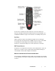
Key Function INCRM, DECRM, or ENTER Once the desired limit, position, or parameter is visible in the display window, press INCRM, DECRM, or ENTER to toggle into edit mode. The lowest adjustable digit will flash on and off. LOCAL Press the LOCAL key for that device to switch the flashing digit to the next higher digit. In this way, it is possible to rapidly adjust any digit of a multi-digit parameter or limit.
3. Set the mechanism to the CCW armed position and insert actuation pins in the holes on either side of the mechanism 45 degrees away. 4. Set the current position displayed by the controller to 000.0 degrees. 5. Test the lower limit by holding down the DEC key, which allows the turntable to travel past the soft limit. The turntable should engage the lower hard limit between -35 and -55 degrees.
Turntable Encoder Calibration Parameter C, the encoder calibration parameter, calibrates the encoder counts to the rotation of the turntable. For the Model 2181, parameter C must be set to 3660. This setting is used to convert the encoder count values returned from a motor base into the corresponding centimeter or degree position reading. For turntables, this represents the number of encoder counts per revolution.
TURNTABLE CALIBRATION EXAMPLE • The turntable is set at the 0 degree position. A piece of tape is placed on the edge of the turntable to line up with the edge of the gearbox cover. The turntable is stopped when the tape travels exactly 360 degrees around. The display on the controller now reads 356.3 degrees, which is recorded. • The table is rotated CCW back to zero. The parameter button is set on the C setting. The C digits display 3430. A new C setting is now calculated: New C = (356.
Do not operate the turntable in a stalled condition. Doing so may cause damage to the drive unit and will void your warranty. Always make sure that the minimum speed setting specified in the S1-S8 parameters is above the minimum value at which your turntable will rotate under normal load. Speed Selection For the variable speed turntable, the Polarization/Flotation button provides the ability to cycle between eight preset speeds.
SSn: Set speed value • n = 1-4 • Command is valid only for a variable speed turntable • Valid speed values are 1-255 • Command Usage: SSn • Example: Output 708, SS1 196 SSn?: Query speed value • n = 1-4 • Command is valid only for a variable speed turntable • Returns a speed value 1-255 • Command Usage: SSn? • Example: Output 708, SS2? Operation | 31
This page intentionally left blank.
Appendix A: Warranty See the Product Information Bulletin included with your shipment for the complete ETS-Lindgren warranty for your ETS-Lindgren Model 2181 Turntable. DURATION OF WARRANTIES FOR MODEL 2181 All product warranties, except the warranty of title, and all remedies for warranty failures are limited to two years.
This page intentionally left blank.
Appendix B: EC Declaration of Conformity The EC Declaration of Conformity is the method by which ETS-Lindgren, L.P. declares that the equipment listed on this document complies with the EMC Directive (EEC/89/336) and Low Voltage Directive (EEC/73/23), including applicable amending directives. Factory Issued by ETS-Lindgren, L.P. ETS-Lindgren, L.P.
REF DRAWING 1. REFER TO SUB ASSY DRAWINGS FOR PARTS AND BOM'S 2. SEE P/N 398797 FOR WIRING DIAGRAM REVISIONS ECN 77.88 TABLE TOP REV 1 82.51 REF DATE DESCRIPTION APPROVED INITIAL BUILD - 17.63 MIN 18.50 MAX 79.75±.25 PIT OPENING DIMENSIONS, REF .25 GAP BETWEEN TABLE TOP AND BRUSH HOLDER .13 FROM TABLE TOP TO TOP OF BRUSH HOLDER EDGE A A SECTION A-A SCALE 1 : 4 2 1 3 1 112197 KIT,SHIPPING,2181-2.0 TURNTABLE 2 1 112196 SUB-ASSY,TOP,TURNTABLE,2181-2.0 1 1 112195 TURNTABLE,2181-2.
REF DRAWING REVISIONS ECN 1. BREATHER PLUG ON GEARBOX TO BE RELOCATED TO TOP OF GEARBOX REV 1 DATE DESCRIPTION APPROVED INITIAL BUILD - 17 19 2 34 29 31 30 34 16 32 34 7 3 6 13 24 23 24 23 20 SEE NOTE 1 27 28 27 14 8 4 32 18 12 22 33 34 10 SPACERS SHOWN FOR REF ONLY, PART OF SHIPPING KIT 43 42 41 40 39 38 37 36 35 34 33 32 31 30 29 28 27 26 25 24 23 22 21 20 19 18 17 16 15 14 13 12 11 10 9 8 7 6 5 4 3 2 1 1 1 1 24 4 1 1 1 25 .
REF DRAWING REVISIONS ECN REV 1 19 25 9 5 DATE DESCRIPTION APPROVED INITIAL BUILD - 13 17 10 20 21 24 17 18 2 11 8 1 26 7 6 12 3 27 26 25 24 23 22 21 20 19 18 17 15 14 13 12 11 10 9 8 7 6 5 4 3 2 1 ITEM# 23 22 15 14 4 BEARING SHOWN FOR REFERENCE ONLY 1 12 8 18 108 80 12 32 8 4 2 6 2 1 6 1 1 1 1 4 6 6 18 6 1 6 QTY 920250 911001 910930 910923 910714 910652 910536 910373 910368 910241 880352 760275 705421 112215 112209 112208 112207 112206 112205 112204 110405 110059 109960 109333 10892
REF DRAWING REVISIONS ECN 1. REFER TO SUB ASSY DRAWINGS FOR PARTS AND BOM'S 2. SEE P/N 398797 FOR WIRING DIAGRAM REV 1 APPROVED DATE DESCRIPTION INITIAL BUILD - 117.22 TABLE TOP 121.82 REF 17.63 MIN 18.50 MAX 119.12±.25PIT OPENING DIMENSION, REF .25 GAP BETWEEN TABLE TOP AND BRUSH HOLDER .13 FROM TABLE TOP TO TOP OF BRUSH HOLDER EDGE A A SECTION A-A SCALE 1 : 4 1 2 3 1 112338 KIT,SHIPPING,2181-3.0 TURNTABLE 2 1 112337 SUB-ASSY,TOP,TURNTABLE,2181-3.0 1 1 112195 TURNTABLE,2181-2.
REF DRAWING REVISIONS ECN REV 28 15 10 33 16 25 9 APPROVED INITIAL BUILD 1 3 DATE DESCRIPTION - 34 5 27 17 29 31 18 28 1 31 4 21 8 BEARING REF ONLY 11 2 12 24 6 7 32 19 20 30 CASTER SPACER STRUT REF ONLY 35 34 33 32 31 30 29 28 27 26 25 24 23 22 21 20 19 18 17 16 15 14 13 12 11 10 9 8 7 6 5 4 3 2 1 1 8 18 156 96 96 24 68 8 96 4 24 12 96 2 8 6 1 1 1 1 24 12 6 6 6 1 4 12 12 6 18 1 12 12 920250 910930 910923 910714 910709 910652 910536 910373 910368 910367 910241 910173 8911
REF DRAWING 1. REFER TO SUB ASSY DRAWINGS FOR PARTS AND BOM'S 2. SEE P/N 398797 FOR WIRING DIAGRAM REVISIONS ECN 156.60 TABLE TOP REV 17.63 MIN 18.50 MAX 1 DATE DESCRIPTION APPROVED INITIAL BUILD - 161.20 REF 158.50±.25 PIT OPENING DIMENSION, REF .25 GAP BETWEEN TABLE TOP AND BRUSH HOLDER .13 FROM TABLE TOP TO TOP OF BRUSH HOLDER EDGE A A SECTION A-A SCALE 1 : 4 1 2 3 1 112451 KIT,SHIPPING,2181-4.0 TURNTABLE 2 1 112450 SUB-ASSY,TOP,TURNTABLE,2181-4.
REF DRAWING REVISIONS ECN 27 25 21 3 33 34 9 15 REV 1 6 16 DATE DESCRIPTION APPROVED INITIAL BUILD - 17 30 14 28 29 28 28 18 10 8 1 2 35 34 33 32 31 30 29 28 27 26 25 24 23 22 21 20 19 18 17 16 15 14 13 12 11 10 9 8 7 6 5 4 3 2 1 ITEM# 11 5 4 32 19 20 31 22 26 CASTER SPACER STRUT SHOWN REF ONLY GAUGE PLATE ASSY SHOWN REF ONLY 7 13 12 23 24 BEARING SHOWN REF ONLY 1 8 18 216 150 24 116 96 8 96 4 24 12 96 2 41.5 6 6 1 1 1 1 24 12 6 6 1 10 12 6 18 12 1 12 12 112450/QTY.
REF DRAWING 1. REFER TO SUB ASSY DRAWINGS FOR PARTS AND BOM'S 2. SEE P/N 398797 FOR WIRING DIAGRAM REVISIONS ECN 201.45 REF REV 1 198.75±.25 PIT OPENING DIMENSION, REF DESCRIPTION INITIAL BUILD DATE APPROVED - - 17.63 MIN 18.50 MAX 196.85 TABLE TOP .25 GAP BETWEEN TABLE TOP AND BRUSH HOLDER .13 FROM TABLE TOP TO TOP OF BRUSH HOLDER EDGE A A SECTION A-A SCALE 1 : 4 1 2 3 1 113180 KIT,SHIPPING,2181-5.0 TURNTABLE 2 1 113179 SUB-ASSY,TOP,TURNTABLE,2181-5.
REF DRAWING REVISIONS 19 12 26 3 35 22 18 34 28 8 13 19 ECN 5 14 18 REV 1 15 DATE DESCRIPTION APPROVED INITIAL BUILD - 31 19 29 18 18 29 18 30 19 19 18 7 19 17 2 36 35 34 33 32 31 30 29 28 27 26 25 24 23 22 21 20 19 18 17 16 15 14 13 12 11 10 9 8 7 6 5 4 3 2 1 1 4 9 16 33 6 25 20 21 32 OUTER GAUGE PLATE SHOWN REF ONLY 23 27 ITEM# 11 THIRD ANGLE PROJECTION 10 GAUGE PLATE ASSY SHOWN REF ONLY 1 8 18 288 160 12 272 120 8 192 4 24 24 192 2 52 12 6 6 12 24 1 1 1 1 4