Model 2188 Series Multi-Axis Positioning System (MAPS) User Manual
ETS-Lindgren L.P. reserves the right to make changes to any products herein to improve functioning or design. Although the information in this document has been carefully reviewed and is believed to be reliable, ETS-Lindgren does not assume any liability arising out of the application or use of any product or circuit described herein; nor does it convey any license under its patent rights nor the rights of others. All trademarks are the property of their respective owners.
Table of Contents Notes, Cautions, and Warnings ......................................................................... v 1.0 Introduction ................................................................................................... 7 MAPS Models ........................................................................................................................... 7 Model 2110 Light Duty MAPS ......................................................................................
This page intentionally left blank.
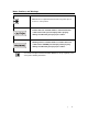
Notes, Cautions, and Warnings Note: Denotes helpful information intended to provide tips for better use of the product. Caution: Denotes a hazard. Failure to follow instructions could result in minor personal injury and/or property damage. Included text gives proper procedures. Warning: Denotes a hazard. Failure to follow instructions could result in SEVERE personal injury and/or property damage. Included text gives proper procedures.
This page intentionally left blank.
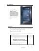
1.0 Introduction The ETS-Lindgren Multi-Axis Positioning System (MAPS™) is designed to perform measurements of spherical antenna patterns as well as total and effective isotropic radiated power of wireless devices. The MAPS provides independent rotation in both azimuth and orthogonal axes. Medium duty MAPS with optional SAM phantom head MAPS Models Three models of MAPS are available. Each model provides a vertical support column to support the Equipment Under Test (EUT).
Part Description Part Number Fiber optic cables, installation hardware, fiber optic feedthrough connectors 110084 MODEL 2115 MEDIUM DUTY MAPS The Model 2115 medium duty MAPS is equipped with mounting plates to secure EUT or a Specific Anthropomorphic Mannequin (SAM) phantom head up to 11.3 kg (25.0 lbs). The SAM phantom head for testing wireless handsets is optional.
The following steps were taken to minimize potential radio frequency (RF) obstruction or distortions of RF signals from low-directive wireless transmit antennas: • The use of minimum composite tube materials to fabricate the rotating shaft and EUT mounts. • RF cable connection to the EUT is made through a 1.2-inch hole provided in the center of the roll axis shaft. The resultant system test data shows virtually no RF interference from the light duty MAPS.
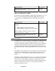
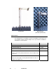
Light Duty Mast Medium Duty Mast (shown with optional mount) Optional Items The following items are available as options to the MAPS. Custom options are also available. Contact your ETS-Lindgren sales representative for additional information on custom options.
Optional Part Description Part Number Free-Space Mount Kit 107549 • • Light duty free-space mount kit is included with all light duty mast assemblies Not compatible with medium duty MAPS 2115 mast assembly Free-Space Mount Kit • • 107559 Medium duty free-space mount kit is not included with medium duty mast assembly Not compatible with light duty MAPS 2110 mast assembly Laptop Mount for medium duty MAPS 2115 • • 108279 To mount laptop or similar device EUT rotation axis is at center of EUT Mount
ETS-Lindgren Product Information Bulletin See the ETS-Lindgren Product Information Bulletin included with your shipment for the following: 12 | • Warranty information • Safety, regulatory, and other product marking information • Steps to receive your shipment • Steps to return a component for service • ETS Lindgren calibration service • ETS Lindgren contact information Introduction
2.0 Maintenance Before performing any maintenance, follow the safety information in the ETS-Lindgren Product Information Bulletin included with your shipment. Do not perform maintenance while MAPS is operating. During maintenance, disconnect power for safety. WARRANTY Only qualified individuals should conduct maintenance inspections or perform maintenance on the MAPS. Regular maintenance will prolong the serviceable life of the turntable.
Annual Maintenance Perform the following maintenance every 12 months after the MAPS is placed into service: 14 • Use a good quality bearing grease to lubricate the main bearing race. The grease fittings are located inside the race, 90° apart, under the top. Three discharges from the grease gun in each fitting are adequate. • Use a good quality grease to lubricate the chain and sprocket of the chain drive.
MAPS Maintenance Log Item Routine Bi-Annual Annual Routine Bi-Annual Annual Routine Bi-Annual Annual Routine Maintenance Check absorber for loose or damaged pieces Check for excess rotation in each axis Check MAPS for loose or damaged parts Bi-Annual Maintenance Grease the casters Annual Check Lubricate the main bearing race Lubricate chain and sprocket and check tension of the chain drive Maintenance | 15
This page intentionally left blank.
3.0 Specifications MAPS Electrical Specifications Nominal AC Voltage: 208–230 VAC Input Frequency: 50/60 Hz Current Rating: 10 amp service Phase: Single MAPS Physical Specifications See the assembly drawings located in the back pocket of the manual for additional dimensions. Unit Diameter: 160.02 cm 63 in Typical Turntable Platform Height: 36.96 cm 14.55 in Approximate Installed Unit Weight: 453.
This page intentionally left blank.
4.0 Installation Before connecting any components, follow the safety information in the ETS-Lindgren Product Information Bulletin included with your shipment. WARRANTY Proper installation of the MAPS directly affects performance. The installation of the MAPS must be performed by factory installation specialists or individuals authorized by ETS-Lindgren to perform installation. This information provided in this manual is intended to be used only by those installation specialists.
Reference Point If installing the MAPS in an existing chamber: Remove the absorber from the floor and lower wall areas prior to installation to avoid damage to the absorber. 1. Locate the reference point. It is generally located along the bore sight axis of the range antenna. See Bore Sight and Leveling on page 23 for additional information regarding bore sight. 2. With permanent marker, place an X on the floor of the chamber at the reference point. 3. Draw a 47-in (1.
5. The MAPS drive units are designed to move from the shipping container to the chamber floor as a single unit. If you cannot move it as a single unit without causing damage, separate the upper drive unit. See Upper Drive Unit Removal on page 22. 6. Place on the chamber floor within the drawn circle. When installing the turntable on modular shielding, do not drill anchor holes through the floor joint strips. Use the shim plates provided. 7.
9. When all anchor plates are securely mounted, remove the 1/4–20 screws that hold the anchor plates to the base. Discard the screws. 10. Use a bubble level to verify the turntable unit is flat. This is a preliminary check only; final leveling of the turntable will be completed in a later step. 11. Use shim plates to level the table. The shim plates will remain in place after the installation.
14. Remove the bracket mounted on the drive unit that is attached to cable carrier. Two #6 screws hold the bracket to the unit. 15. Remove the cable clip holding the power cable. 16. Remove the bracket on the opposite side of the unit that ties the drive unit to the turntable top. This temporary bracket holds the unit in place for shipping. 17. Turn the brake knob to release the drive unit and allow it to move toward center of table.
To make sure the MAPS is level with the antennas in the chamber and is accurately centered in the chamber, install the mast(s). Bore sight of the MAPS requires a five-beam laser level. Following are the typical installation steps used to achieve bore sight for a MAPS unit. 1. Locate and mark the center of the chamber wall opposite the range antenna mounted in the chamber end wall. Marking may require the removal of absorber. This applies for both rectangular and tapered chambers.
Fit the flexible couplings of the mast and turntable together 3. Install the MAPS mast(s). Line up the flexible couplings and slide the mast into position. Slide the aluminum knobs over the collar of the mast 4. After the couplings are aligned and the mast is fitted securely to the turntable top, slide the aluminum hand knobs over the collar and tighten.
Align laser through the mast mount to the center of the chamber 5. When the knobs are securely in place, place the MAPS system so that the center of the horizontal axis is aligned with the laser beam. Small height corrections may be necessary. For information, see Leveling and Height Adjustment on page 28. After the system is leveled, additional height corrections may be required.
Laser and tripod on turntable top (Shown with optional dipole mount plate) 6. Mount the laser onto a tripod, and then place it on the turntable top. 7. Sight one horizontal laser in line with the antenna mounted in the end wall of the chamber. Align the opposite side of the horizontal laser through the mounting gear of the MAPS to the center of the opposite end wall and to the reference point previously marked.
LEVELING AND HEIGHT ADJUSTMENT If during the bore sight process it is determined that the MAPS system must be leveled or the height adjusted, follow these steps. Loosen collar on the anchor shafts 1. Use a 3/16 hex key wrench to loosen the collar on the anchor shafts. Remove flange nuts, then raise or lower leveling bolts 2. Use an open-ended wrench to loosen the flange nuts on all leveling bolts. 3. Lower or raise the leveling bolts to set the turntable to the correct height.
If installing the MAPS in a pit, mark the amount required to raise the unit up to level. Remove the top of the turntable and begin leveling. 5. Verify that the unit is level. Attach the wooden turntable top (Shown with optional dipole mount base) 6. Position the wooden turntable top on the turntable base. 7. Use a 5/16 Allen wrench to tighten the bolts. 8. Secure the turntable top seams in place with a Phillips screwdriver.
Position the actuating pins on each side of the limit switch access port 9. Verify the access port is located over the limit switch. 10. Position the actuating pins in the holes on each side of the access port. Controller Interface For information about connecting fiber optic cables from the MAPS to the Model 2090 Multi-Device Controller (or next generation ETS-Lindgren controller, if applicable), see the controller manual.
The MAPS is designed to operate using 208–230 VAC single-phase 50 or 60 Hz power. The branch circuit supplying power to the motor bases must be protected from excess current according to local electrical codes. Integral circuit protection is provided in the motor base assembly. Check that the conductor size is adequate for the motor load and the distance from the mains source.
Absorber Installation After the MAPS and mast(s) are leveled and bore sight is achieved, position the absorber that surrounds and covers the unit. For absorber locations, see the Top View of Wood Deck with Absorber Locations assembly drawing located in the back pocket of the manual.
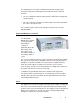
5.0 Operation Before placing into operation, follow the safety information in the ETS-Lindgren Product Information Bulletin included with your shipment. If you are unfamiliar with the operation of the Model 2090 Series Multi-Device Controller (or next generation ETS-Lindgren controller, if applicable), see the manual included with the controller. The manual is also available for download from www.ets-lindgren.com.
Parameter Device 1–Turntable Theta Axis Device 2–Mast Upper Rotation Phi Axis S6 191 191 S7 223 223 S8 255 255 Ac 2.0 2.
Appendix A: Warranty See the Product Information Bulletin included with your shipment for the complete ETS-Lindgren warranty for your MAPS. DURATION OF WARRANTIES FOR MAPS All product warranties, except the warranty of title, and all remedies for warranty failures are limited to two year.
This page intentionally left blank.
Appendix B: Assembly Drawings The following assembly drawings are located in the back pocket of the manual: • 111045 • 109987 • 110073 • 111040 • 111041 • Top View of Wooden Deck with Absorber Locations Assembly Drawings | 37
This page intentionally left blank.
Appendix C: EC Declaration of Conformity EC Declaration of Conformity | 39
REF DRAWING REVISIONS NOTES: 1. SEE SHEET 2 FOR DETAILS 2. INSTALL PULLEY ON OUTPUT SHAFT THAT TURNS IN THE SAME DIRECTION AS THE INPUT SHAFT 3. MATCH DRILL ITEM 11 AND 12 WITH .375 BOTH SIDES. ITEMS 9 AND 10 INSTALL ITEM 15 4 PLACES 48 47 46 45 44 43 42 41 40 39 38 37 36 35 34 33 32 31 30 29 28 27 26 25 24 23 22 21 20 19 18 17 16 15 14 13 12 11 10 9 8 7 6 5 4 3 2 1 ITEM NO. 11 REF ONLY 30 28 39 TRIM BELT TO LENGTH MATCHDRILL BELT WITH BRACKETS 29 27 46 46 ECO# REV 5022 A 4 6 4 .10 1 .
REF DRAWING REVISIONS 40 NOTES: ECO# 19 10 DESCRIPTION DATE APPROVED 21 23 9 REV 42 43 17 44 SEE NOTE 3 15 12 36 24 34 7 16 26 34 18 20 22 11 6 TOP ASSY 45 SEE NOTE 2 32 33 41 38 33 35 33 25 45 2 3 8 32 34 13 31 1 47 45 48 37 4 45 14 45 5 GEARBOX ASSY UNLESS OTHERWISE SPECIFIED: DIMENSIONS ARE IN INCHES TOLERANCES ARE: DECIMALS ANGLES X.XX ± .015 X.XXX ± .005 BOTTOM ASSY 45 ± .5 EMC Test Systems, L.P.
REF DRAWING REVISIONS NOTES: 1. DIMENSION IS FROM MOTORBASE COVER TOP TO COUPLING HUB TOP. 18 REV 5068 A DESCRIPTION RELEASED DATE APPROVED 3/23/06 RBG 27 19 20 21 11 ECO# 9 25 6 1.63 2 15 1.
REF DRAWING REVISIONS NOTES: 1. SOME PARTS SHOWN IN EXPLODED VIEW FOR PART CLARITY. 2. LINEAR SLIDES TO BE SET WITH MOTORBASE ATTACHED TO THEM FOR PROPER ALIGNMENT AND ADJUSTMENT TO ITEM 3 PRIOR TO FINAL ASSY. 3. NOT ALL HARDWARE SHOWN. ECO# REV 5068 A DESCRIPTION RELEASED DATE APPROVED 3/23/06 RBG 5 6 17 .
REF DRAWING REVISIONS NOTES: 1. REFER TO ASSY'S, SUB-ASSY'S, AND KITS FOR OTHER NOTES AND HARDWARE NEEDED FOR FINAL ASSY AND INSTALLATION REQUIREMENTS. ECO# REV 5122 A 5294 5600 DESCRIPTION DATE APPROVED RELEASED 6/28/06 RBG B P/N 910159 WAS 910714, UPDATED HW PER VAULT HARDWARE 4/20/07 RBG C ADDED 506179,506180,675319. P/N 910713 QTY WAS 3 12/12/08 RBG 63.00 (WOODEN DECK) 7.80 14.43 5.88 .
REF DRAWING REVISIONS ECO# NOTES: 1. BRACKET ALONG WITH HARDWARE IS USED TO TIE SLIDER ASSY DOWN PRIOR TO CRATING AND BEFORE SHIPPING. MOVE SLIDER ASSY INTO POSITION AND APPLY 6-32 SCREWS INTO APPROPRIATE HOLES IN SLIDER ASSY. APPLY BREAK ON OPPOSITE SIDE TO ENSURE SLIDER ASSY STAYS IN FORWARD POSITION.
REF DRAWING REVISIONS NOTES: 1. SEE SHEET 2 FOR DETAILS 2. INSTALL PULLEY ON OUTPUT SHAFT THAT TURNS IN THE OPPOSITE DIRECTION OF THE INPUT SHAFT 16 REF ONLY 12 26 28 12 27 29 TRIM BELT TO LENGTH MATCHDRILL BELT WITH BRACKETS 30 ECO# REV 5022 A .67 FROM BOTTOM OF GEARBOX FLANGE TO TOP OF COUPLING HUB X.XX ± .015 X.XXX ± .005 FINISH NONE ± .5 APPROVALS DRAWN RBG CHECKED DATE 10/10/05 .10 2 2 2 1 2 6 1 4 4 3 10 2 2 4 14 2 1 1 1 1 12.
REF DRAWING REVISIONS 31 NOTES: 39 ECO# APPROVED 21 15 46 DATE 34 32 38 DESCRIPTION 40 17 14 REV 22 2 37 31 35 33 25 18 9 7 44 46 14 35 46 20 8 46 35 SEE NOTE 2 36 16 3 46 41 23 6 46 4 43 19 24 31 42 UPPER ASSEMBLY 5 11 GEARBOX ASSEMBLY 10 13 1 EMC Test Systems, L.P. Cedar Park, TX LOWER ASSEMBLY UNLESS OTHERWISE SPECIFIED: DIMENSIONS ARE IN INCHES TOLERANCES ARE: DECIMALS ANGLES X.XX ± .015 X.XXX ± .005 FINISH NONE ± .
REF DRAWING REVISIONS NOTES: THIS DRAWING REPRESENTS THE LOCATIONS OF ABSORBER PARTS ON THE MAPS WOODEN DECK. TO BE USED AS REFERENCE ONLY.