Archived 3/18/10 Model 2087 Electric Powered Turntable 2 & 3 Meter Models MANUAL © EMC TEST SYSTEMS, L.P.
Archived 3/18/10 MODEL 2087 TURNTABLE SERIES EMC Test Systems, L.P. reserves the right to make changes to any products herein to improve functioning, design, or for any other reason. Nothing contained herein shall constitute EMC Test Systems, L.P. assuming any liability whatsoever arising out of the application or use of any product or circuit described herein. EMC Test Systems, L.P. does not convey any license under its patent rights or the rights of others. © Copyright 2002 by EMC Test Systems, L.P.
Archived 3/18/10 MODEL 2087 TURNTABLE SERIES Table of Contents INTRODUCTION ........................................................................................................................................ 1 STANDARD CONFIGURATION .............................................................................................................. 2 OPTIONS ......................................................................................................................................................
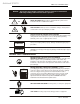
Archived 3/18/10 NOTICE: MODEL 2087 TURNTABLE SERIES This product and related documentation must be reviewed for familiarization with safety markings and instructions before operation. SAFETY SYMBOL DEFINITIONS ! REFER TO MANUAL When product is marked with this symbol refer to instruction manual for additional information. OR HIGH VOLTAGE Indicates presence of hazardous voltage. Unsafe practice could result in severe personal injury or death.
Archived 3/18/10 MODEL 2087 TURNTABLE SERIES Introduction INTRODUCTION The ETS-Lindgren Model 2087 is an electric powered turntable platform system designed to be used with the Model 2090 Positioning Controller for EMI compliance testing. The Model 2087 is available in 2.03 and 3.03 meter sizes, both designed for indoor or outdoor use. The sectional turntable top surface is made of aluminum. The conductive metal top is fitted with a ground brush to electrically couple the turntable to the ground plane.
Archived 3/18/10 Standard Configuration MODEL 2087 TURNTABLE SERIES STANDARD CONFIGURATION 2 • Turntable assembly • Ground ring assembly with ground brush and floor flange • 230 VAC Electric Motor Unit • Rotational limit adjust switches • Continuous or Non-continuous operation • Ten-meter fiber-optic control cables • Overall height 280 mm (11”) • SCAN and SEEK Capability © EMC TEST SYSTEMS, L.P.
Archived 3/18/10 MODEL 2087 TURNTABLE SERIES Options OPTIONS Model 2090 Positioning Controller: This controller provides control for two separate devices (ETS-Lindgren towers and turntables) in any combination, plus the control of four auxiliary devices. The unit includes a GPIB bus and is compatible with most popular software. Hand Control Unit (HCU): This sturdy, hand-held controller will allow the user to manually operate the table remotely and independently from the Model 2090 Positioning Controller.
Archived 3/18/10 Options MODEL 2087 TURNTABLE SERIES Mounted LISNs: LISNs can be mounted to the underside of some turntables. This option is only practical on larger turntables with sufficient clearance. Additional Fiber Optic Cable: Additional lengths of fiber optic cable may be ordered. 4 © EMC TEST SYSTEMS, L.P.
Archived 3/18/10 MODEL 2087 TURNTABLE SERIES Precautions PRECAUTIONS Read this manual completely before starting installation. This equipment should be installed and operated only by qualified personnel. The electrical installation of this product should be accomplished by an individual who is authorized to so do by the appropriate local authority. The installation should be in compliance with local electrical safety codes. Do not attempt to service unless qualified to do so.
Archived 3/18/10 Turntable Installation Considerations MODEL 2087 TURNTABLE SERIES TURNTABLE INSTALLATION CONSIDERATIONS Pre-planning is essential for a successful installation. Be sure to discuss your requirements will your sales representative and request dimensional drawings prior to construction of your site. POWER AND SIGNAL LINES Conduit Power and signal line paths should be planned in advance. Conduit should be in place before pouring concrete or installing the ground plane.
Archived 3/18/10 MODEL 2087 TURNTABLE SERIES Assembly Instructions ASSEMBLY INSTRUCTIONS The installation of turntables 2 meters and larger will be performed by a factory installation specialist or by individuals who have been authorized by ETS-Lindgren to do such work. Proper installation of the turntable directly affects performance. The following installation information is provided to familiarize the user of the turntable with the installation process. 1. Uncrate all parts.
Archived 3/18/10 Assembly Instructions MODEL 2087 TURNTABLE SERIES 6. Connect the fiber-optic control cable and install the power connection per local electrical code. The standard power configuration is 230 VAC 50/60 Hz. CAUTION Electrical connection should only be performed by a qualified electrician and subject to local electrical codes. CAUTION Keep all body parts away from the drive pinion when the turntable is energized. 7.
Archived 3/18/10 MODEL 2087 TURNTABLE SERIES Electrical Installation 5. To maintain the proper spacing between the turntable and the ground ring, it may be necessary to shim or pull the ground ring into position before fastening. ELECTRICAL INSTALLATION CAUTION It is important that this electrical installation procedure be performed by a qualified electrician, in accordance with local and national electrical standards prior to energizing the unit.
Archived 3/18/10 Electrical Installation MODEL 2087 TURNTABLE SERIES Should it be desired to operate at 115 VAC, jumpers in the relay enclosure assembly can be reconfigured. Consult the factory for safe and proper modification of the jumper configuration. Prior to changing these jumpers, insure that power has not been supplied or has been safely removed from the assembly. The jumpers provide a means for applying the proper voltage to both the internal power supply and to the electric motor.
Archived 3/18/10 MODEL 2087 TURNTABLE SERIES Setting Travel Limits fiber optic cables as straight as possible from the connector to the protective sheath. Using the Model 2090 Position Controller (or hand controller), rotate the motor base shaft to verify proper operation. Run the motorbase down to the lower limit CCW and then back it off from the lower limit just a bit. The previous step will help when it is time to set the rotation limits for the turntable.
Archived 3/18/10 Setting Travel Limits MODEL 2087 TURNTABLE SERIES 5. Disengaged the limit mechanism by loosening the inline coupler and sliding the coupler at least ¼ inch back from its mate to disengage the drive teeth. 6. Retighten the shaft set screws on the coupler. 7. Reinstall the cover and the adjustment knobs. Once limits have been set or disengaged using the above procedure, return the turntable to its original position by replacing the top section. 12 © EMC TEST SYSTEMS, L.P.
Archived 3/18/10 MODEL 2087 TURNTABLE SERIES Operation OPERATION Please refer to the Model 2090 Positioning Controller manual if you are unfamiliar with the operation of the unit. A 2090 manual is included with each 2090 shipment and is also available for download from our website: www.ets-lindgren.com. With the assembly complete the Model 2090 controller will need to be connected to the unit and power applied to both the motor base and controller in order to continue.
Archived 3/18/10 Operation MODEL 2087 TURNTABLE SERIES RECOMMENDED PARAMETERS FOR THE MODEL 2090 POSITIONING CONTROLLER Parameter P1 P2 P3 P5 P8 P9 b1 c S0 Oc Value 0 0 000 1 2.5 9 000 3600 -1 On DEVICE 2 Description Turntable Standard Turntable Infinite Scan Count Non-continuous rotation 2.
Archived 3/18/10 MODEL 2087 TURNTABLE SERIES Operation toggle into edit mode. The lowest adjustable digit will flash on and off. Pressing the LOCAL key for that device will switch the flashing digit to the next higher digit. In this way, it is possible to rapidly adjust any digit of a multi-digit parameter or limit. TURNTABLE ENCODER CALIBRATION C Refers to the encoder calibration parameter.
Archived 3/18/10 Operation MODEL 2087 TURNTABLE SERIES meter and the 2090 can not correct for it. In this case, contact ETS-Lindgren for assistance. 6. Enter this value for the encoder calibration value and reset the limits and position information. 7. Test the turntable by moving it a complete revolution and comparing the alignment marks. It may be necessary to adjust the encoder calibration value up or down slightly depending on the result.
Archived 3/18/10 MODEL 2087 TURNTABLE SERIES Operation SETTING CURRENT POSITION ON 2090 The total travel between the mechanical limits is typically set between 370 and 400 degrees at the factory. Set the 0 degree position on the 2090 so that the 2090 moves the table between the mechanical limits without engaging them in normal operation. EXAMPLE (CW - clockwise, CCW - counterclockwise) The table is rotated CCW until it stops at the mechanical limit. The table current position is then set at 0.
Archived 3/18/10 Hand Control Unit MODEL 2087 TURNTABLE SERIES HAND CONTROL UNIT To connect the Hand Control Unit (HCU), remove the connector cap on the motor base. Plug the cable receptacle from the hand control unit into the electrical enclosure and screw connectors completely together. The HCU is now ready to operate. Be sure to coordinate use of the unit with the operator of the Model 2090 Positioning Controller.
Archived 3/18/10 MODEL 2087 TURNTABLE SERIES Recommended Maintenance RECOMMENDED MAINTENANCE Regular maintenance will prolong the effective operation and reliability of your turntable. Follow this recommended schedule. CAUTION Do not perform maintenance while the turntable is operating. EVERY SIX MONTHS Adjust the encoder chain. The chain should have no more than 20mm (1/8”) looseness when flexed to a point halfway between the two sprockets.
Archived 3/18/10 Specifications MODEL 2087 TURNTABLE SERIES SPECIFICATIONS ELECTRICAL Drive Speeds Single (Standard) Nominal AC Voltage Input Frequency Current Rating AMP RPM Phase 208-230 VAC 50/60 Hz 20 amp service 4 1.9 Single (1) Variable (Optional) 208-230 VAC 50/60 Hz 20 amp service 8 .5/2.
Archived 3/18/10 MODEL 2087 TURNTABLE SERIES Warranty Statement WARRANTY STATEMENT EMC Test Systems, L.P., hereinafter referred to as the Seller, warrants that standard EMCO products are free from defect in materials and workmanship for a period of two (2) years from date of shipment.
Archived 3/18/10 Illustrations MODEL 2087 TURNTABLE SERIES ILLUSTRATIONS 22 © EMC TEST SYSTEMS, L.P.
Archived 3/18/10 MODEL 2087 TURNTABLE SERIES © EMC TEST SYSTEMS, L.P.
Archived 3/18/10 Illustrations 24 MODEL 2087 TURNTABLE SERIES © EMC TEST SYSTEMS, L.P.
Archived 3/18/10 MODEL 2087 TURNTABLE SERIES © EMC TEST SYSTEMS, L.P.
Archived 3/18/10 Illustrations 26 MODEL 2087 TURNTABLE SERIES © EMC TEST SYSTEMS, L.P.
Archived 3/18/10 MODEL 2087 TURNTABLE SERIES © EMC TEST SYSTEMS, L.P.
Archived 3/18/10 Illustrations 28 MODEL 2087 TURNTABLE SERIES © EMC TEST SYSTEMS, L.P.
Archived 3/18/10 MODEL 2087 TURNTABLE SERIES © EMC TEST SYSTEMS, L.P.
Archived 3/18/10 Illustrations 30 MODEL 2087 TURNTABLE SERIES © EMC TEST SYSTEMS, L.P.