Archived 3/18/10 Model 2075 MiniMast™ MANUAL © EMC TEST SYSTEMS, L.P.
Archived 3/18/10 MODEL 2075 MINIMAST™ EMC Test Systems, L.P. reserves the right to make changes to any products described herein in order to improve function, design or for any other reason. Nothing contained herein shall constitute EMC Test Systems, L.P. assuming any liability whatsoever arising out of the application or use of any product or circuit described herein. EMC Test Systems, L.P. does not convey any license under its patent rights or the rights of others.
Archived 3/18/10 MODEL 2075 MINIMAST™ Table of Contents INTRODUCTION............................................................................................................. 1 STANDARD CONFIGURATION .................................................................................. 2 MODEL 2075 OPTIONS ................................................................................................. 3 PRECAUTIONS ...........................................................................................
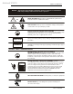
Archived 3/18/10 NOTICE: MODEL 2075 MINIMAST™ This product and related documentation must be reviewed for familiarization with safety markings and instructions before operation. SAFETY SYMBOL DEFINITIONS ! REFER TO MANUAL When product is marked with this symbol refer to instruction manual for additional information. OR HIGH VOLTAGE Indicates presence of hazardous voltage. Unsafe practice could result in severe personal injury or death.
Archived 3/18/10 MODEL 2075 MINIMAST™ Introduction INTRODUCTION The ETS-Lindgren Model 2075 MiniMast™ is a portable electric powered mast and platform system designed to be used with the Model 2090 Positioning Controller for EMI compliance testing. The MiniMast™ is designed for antenna scanning from 1m to 2m, with a 2 m mast extension included so that 1m to 4 m scans can be performed. The mast, carrier, platform, lifting rope and guying system are non-conductive and non-magnetic.
Archived 3/18/10 Standard Configuration MODEL 2075 MINIMAST™ A safety brake is mounted on the carrier assembly. In the event that the carrier is released from its rope suspension, a springloaded lever jams the brake into position against the mast and locks the carrier so that further vertical movement is restricted. Mylar rope guy lines are provided for outdoor installations and must be firmly anchored to provide vertical stability.
Archived 3/18/10 MODEL 2075 MINIMAST™ Model 2075 Options MODEL 2075 OPTIONS Model 2090 Positioning Controller: This controller provides control for two separate devices (i.e. towers and turntables) in any combination, plus the control of four auxiliary devices via a fiber optic interface. The unit includes a GPIB connection and is compatible with most popular EMI measurement software.
Archived 3/18/10 Precautions MODEL 2075 MINIMAST™ PRECAUTIONS Read this manual completely before starting installation. This equipment should be installed and operated only by qualified personnel. The electrical installation of this product should be accomplished by an individual who is authorized to do so by the appropriate local authority. The installation should be in compliance with local electrical safety codes. Do not attempt to service the unit unless qualified to do so.
Archived 3/18/10 MODEL 2075 MINIMAST™ Precautions The fiber optic cable must be looped through the “P” clip installed on the front panel. Failure to do so will increase the chance of cable being accidentally pulled, thus breaking the fiber optic connectors. © EMC TEST SYSTEMS, L.P.
Archived 3/18/10 Assembly Instructions MODEL 2075 MINIMAST™ ASSEMBLY INSTRUCTIONS The Model 2075 is shipped partially assembled. It is anticipated that the assembly process will take no longer than one hour. Ensure that a clear area is available to unpack and assemble the MiniMast™. Prior to starting the assembly process, open the shipping container and check all parts for any shipping damage. NOTE: Do not discard any packing material until the tower is fully installed and operational.
Archived 3/18/10 MODEL 2075 MINIMAST™ Assembly Instructions 5. Should guying of the mast be required, attach the guy ropes to the mast pulley section now. Guying is recommended when the mast is used for the full 4 meter scan height and for outdoor applications. 6. There are two bolts that when inserted and tightened will secure the mast into the support structure. Making sure the holes on the mast and the support structure are aligned, lift and place the mast into the support.
Archived 3/18/10 Assembly Instructions MODEL 2075 MINIMAST™ 12. Connect the free end of the lifting rope to the carrier brake using the phenolic rope clamp. When connecting the rope to the carrier, lift the carrier slightly and connect the rope so that it is taut. 13. To set the antenna’s vertical position, measure the distance from the antenna (i.e. antenna centerline) to the ground plane.
Archived 3/18/10 MODEL 2075 MINIMAST™ Electrical Installation ELECTRICAL INSTALLATION The Model 2075 is configured to operate using either 115 or 230 VAC, single phase, 50/60 Hz service. The voltage setting is accomplished by switching two voltage select switches which are accessible from the outside of the motor base assembly. The switches are located adjacent to one another on the side of the motor base enclosure immediately below the lid of the enclosure.
Archived 3/18/10 Electrical Installation MODEL 2075 MINIMAST™ branch circuit of adequate current capacity to keep voltage drop to a minimum during startup and running. Check that the conductor size is adequate for the motor load and the distance from the mains source. Improperly sized conductors will lead to a high voltage drop in the power conductors and cause reduced starting torque and premature motor failure.
Archived 3/18/10 MODEL 2075 MINIMAST™ Electrical Installation 5. The control relay PCB assembly inside the enclosure is connected to the enclosure via an L-shaped bracket. It will be necessary to remove the mounting screws which hold the bracket to the bottom of the housing in order to gain access to the wires connected to the base of the filter. Do not disconnect wires from the relay assembly. Locate the two screws that secure the L-shaped bracket in place, loosen and remove them.
Archived 3/18/10 Electrical Installation MODEL 2075 MINIMAST™ coating) conduit fitting should be attached in the strain relief hole. Moisture should not be allowed to penetrate the motor base enclosure as it could damage the components inside. 10. Keep the lead length inside the enclosure to no longer than 4 inches to maintain good EMC performance. The distance from the opening in the conduit fitting to the filter should remain less than 10 cm (4 inches).
Archived 3/18/10 MODEL 2075 MINIMAST™ Electrical Installation CONNECTING THE MODEL 2090 POSITIONING CONTROLLER Any combination of primary devices (towers, turntables, reverberation paddles, MAPS, etc.) can be connected to the two Device Interface ports located on the rear panel of the controller. For easy set up of an EMC facility, it is recommended that the tower be connected to the Device 1 interface port.
Archived 3/18/10 Electrical Installation MODEL 2075 MINIMAST™ turn the knob in the direction indicated by the positive (+) sign. To decrease the amount of travel in either direction, turn the knob in direction indicated by the minus (-) sign. Run the motor base down to the lower limit CCW and then back it off from the lower limit just a bit. 14 © EMC TEST SYSTEMS, L.P.
Archived 3/18/10 MODEL 2075 MINIMAST™ Setting Travel Limits SETTING TRAVEL LIMITS The mechanical limits of the Model 2075 MiniMast™ are located in the motor base on the mast platform. CAUTION Keep all body parts away from the drive components when the tower is energized. Never be directly beneath the carrier at any time. The mechanical limit adjustment knobs are labeled to indicate function.
Archived 3/18/10 About the Brakes MODEL 2075 MINIMAST™ ABOUT THE BRAKES CARRIER SAFETY BRAKE A safety brake is mounted on the carrier assembly. In the event that the carrier is released from its rope suspension, a springloaded lever jams the brake into position against the mast and locks the carrier so that further vertical movement is restricted.
Archived 3/18/10 MODEL 2075 MINIMAST™ Operation NOTE: The dimension for the air gap is a nominal position. Observe the motor starting characteristics after adjusting the gap. The motor should start quickly. If not, increase the air gap by turning the adjusting screw counter-clockwise increments. After the adjustment is complete, replace the brake cover, reconnect the air lines, close and clamp the top of the motor enclosure and replace the brake access cover. © EMC TEST SYSTEMS, L.P.
Archived 3/18/10 Operation MODEL 2075 MINIMAST™ OPERATION Please refer to the Model 2090 Positioning Controller manual if you are unfamiliar with the operation of the unit. A Model 2090 manual is included with each 2090 shipment and it also available for download from our website. EDITING MODEL 2090 POSITIONING CONTROLLER CONFIGURATION PARAMETERS To edit a configuration parameter, press the PARAM key to display the current parameter.
Archived 3/18/10 MODEL 2075 MINIMAST™ Operation encoder counts per meter. Using this parameter, a variety of standard, retrofit, and custom devices can be used. The setting for the Model 2075 series towers is : 1620 If the given value does not appear to work correctly, the encoder calibration value can be determined using the following procedure: 1. Set the encoder calibration value to 1000. 2.
Archived 3/18/10 Operation MODEL 2075 MINIMAST™ ANTENNA MOUNTING INSTRUCTIONS Antennas can be mounted to the assembly using either the 7/8-14 thread which is common on EMCO brand antennas, or the ¼-20 thread which is another common size. The antenna should be mounted on the boom as close to the carrier as possible. Insert the mounting knobs through the holes on the boom and align the mounting holes on the antenna with the threaded end of the mounting knobs.
Archived 3/18/10 MODEL 2075 MINIMAST™ Operation complete stop. Press the power button on the Model 2090 Positioning Controller to turn it off. © EMC TEST SYSTEMS, L.P.
Archived 3/18/10 Hand Control Unit MODEL 2075 MINIMAST™ HAND CONTROL UNIT To connect the Hand Control Unit (HCU), remove the connector cap on the motor base. Plug the cable receptacle from the hand control unit into the electrical enclosure and screw connectors completely together. The HCU is now ready to operate. Be sure to coordinate use of the unit with the operator of the Model 2090 Positioning Controller. To allow the HCU to operate, push the control switch from MAIN to HAND.
Archived 3/18/10 MODEL 2075 MINIMAST™ Recommended Maintenance RECOMMENDED MAINTENANCE Regular maintenance will prolong the service of your mast assembly. Follow this recommended schedule. CAUTION Do not perform maintenance while the tower is operating or energized. Prior to beginning normal operation of the mast, check the mast and lift system for any signs of damage or excessive wear. If guyed, insure that all guy ropes are securely fastened.
Archived 3/18/10 Recommended Maintenance MODEL 2075 MINIMAST™ lubricated and sealed at the factory. Under normal conditions, it should not require servicing during its life. Check the electrical cabling to the motor base for frayed and worn insulation. EVERY 12 MONTHS Check the mast parts for signs of wear and fatigue. Check the pads on the electrical brake assembly in the motor base for signs of wear or potential failure.
Archived 3/18/10 MODEL 2075 MINIMAST™ Specifications SPECIFICATIONS ELECTRICAL Nominal AC Voltage Input Frequency Current Rating Phase 115/230 VAC 50/60 Hz 20 amp service Single (1) Scan Range Mast Height Carrier load rating Required air pressure 2 meters or 4 meters 2.5 meters or 4.5 meters 10.0 kg (22.0 lb) 60-80 psi (410-550 kPa) MECHANICAL © EMC TEST SYSTEMS, L.P.
Archived 3/18/10 Warranty Statement MODEL 2075 MINIMAST™ WARRANTY STATEMENT EMC Test Systems, L.P., hereinafter referred to as the Seller, warrants that standard EMCO products are free from defect in materials and workmanship for a period of two (2) years from date of shipment.
Archived 3/18/10 MODEL 2075 MINIMAST™ EUROPEAN COMMUNITY DECLARATION OF CONFORMITY EUROPEAN COMMUNITY DECLARATION OF CONFORMITY The EC Declaration of Conformity is the method by which EMC Test Systems, L.P. declares that the equipment listed on this document complies with the EMC and Low-voltage Directives. Factory: EMC Test Systems, L.P. P.O. Box 80589 Austin, Texas USA 78708-0589 Issued by: EMC Test Systems, L.P. P.O.
Archived 3/18/10 Illustrations MODEL 2075 MINIMAST™ ILLUSTRATIONS 28 © EMC TEST SYSTEMS, L.P.
Archived 3/18/10 Illustrations E MC Test S ystems, L.P. Cedar P ark, TX Lindgren- RF Enclosures G lend ale Hts, IL MODEL 2075 MINIMAST™ © EMC TEST SYSTEMS, L.P.
Archived 3/18/10 MODEL 2075 MINIMAST™ EM C Test S ystems, L.P. Cedar P ark, TX Lindgren- RF Enclosures G lend ale Hts, IL Illustrations 30 © EMC TEST SYSTEMS, L.P.
Archived 3/18/10 Illustrations E MC Test S ystems, L.P. Cedar P ark, TX Lindgren- RF Enclosures G lend ale Hts, IL MODEL 2075 MINIMAST™ © EMC TEST SYSTEMS, L.P.
Archived 3/18/10 Illustrations 32 MODEL 2075 MINIMAST™ © EMC TEST SYSTEMS, L.P.