Archived 3/18/10 Model 2065 LoPro Turntable Electric-powered 1.2m Turntable MANUAL © EMC TEST SYSTEMS, L.P.
Archived 3/18/10 MODEL 2065 LOPRO TURNTABLE EMC Test Systems, L.P. reserves the right to make changes to any products herein to improve functioning, design, or for any other reason. Nothing contained herein shall constitute EMC Test Systems, L.P. assuming any liability whatsoever arising out of the application or use of any product or circuit described herein. EMC Test Systems, L.P. does not convey any license under its patent rights or the rights of others. © Copyright 2002 by EMC Test Systems, L.P.
Archived 3/18/10 MODEL 2065 LOPRO TURNTABLE Table of Contents INTRODUCTION ........................................................................................................................................ 1 MODEL 2065 OPTIONS ............................................................................................................................. 3 PRECAUTIONS .........................................................................................................................................
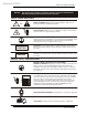
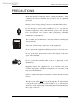
Archived 3/18/10 NOTICE: MODEL 2065 LOPRO TURNTABLE This product and related documentation must be reviewed for familiarization with safety markings and instructions before operation. SAFETY SYMBOL DEFINITIONS ! REFER TO MANUAL When product is marked with this symbol refer to instruction manual for additional information. OR HIGH VOLTAGE Indicates presence of hazardous voltage. Unsafe practice could result in severe personal injury or death.
Archived 3/18/10 MODEL 2065 LOPRO TURNTABLE Introduction INTRODUCTION The Model 2065 is an electric-powered turntable platform system designed to be used with the Model 2090 Positioning Controller for EMI compliance testing. The Model 2065 Turntable is a lowprofile design which is constructed of PVC plate with a textured ABS top and other non-metallic components. The 1.2 meter diameter turntable is provided as an easily assembled system which can be disassembled for service or to be moved.
Archived 3/18/10 Introduction MODEL 2065 LOPRO TURNTABLE within the mechanical limits. The mechanical limits are secondary and a safety stop to limit the turntable’s total rotation. Overshoot of the turntable’s rotation is limited by an electric brake which is directly attached to the drive motor. The Model 2090 Positioning Controller compensates for any remaining overshoot by applying an overshoot compensation routine which is accomplished automatically without any user input. 2 © EMC TEST SYSTEMS, L.
Archived 3/18/10 MODEL 2065 LOPRO TURNTABLE Model 2065 Options MODEL 2065 OPTIONS Model 2090 Positioning Controller: This controller provides control for two separate devices (towers and turntables) in any combination, plus the control of four auxiliary devices via a fiber optic interface. The unit includes a GPIB connection and is compatible with most popular EMI measurement software.
Archived 3/18/10 Precautions MODEL 2065 LOPRO TURNTABLE PRECAUTIONS Read this manual completely before starting installation. This equipment should be installed and operated only by qualified personnel. Ensure correct voltage setting is selected on the Motor Base Unit. Do not attempt to service unless qualified to do so. As with any electrical equipment, ensure that electrical power to the unit has been disconnected and secured when performing scheduled maintenance or adjustments.
Archived 3/18/10 MODEL 2065 LOPRO TURNTABLE Precautions The keepers on the outside edge of the turntable should be in place when the turntable is to be moved or relocated. This will prevent damage to the bearings on which the turntable top rotates. © EMC TEST SYSTEMS, L.P.
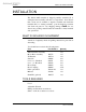
Archived 3/18/10 Installation MODEL 2065 LOPRO TURNTABLE INSTALLATION The Model 2065 turntable is shipped partially assembled. It is anticipated that assembly will take no longer than 1 hour. Ensure that a clear area is available to unpack, assemble and install the turntable. Prior to starting assembly, open the shipping container and check all parts for any shipping damage. NOTE: Do not discard any packing material until the turntable is fully installed and operational.
Archived 3/18/10 MODEL 2065 LOPRO TURNTABLE Electrical Installation ELECTRICAL INSTALLATION CAUTION It is important that this electrical installation procedure be performed by a qualified electrician, in accordance with local and national electrical standards prior to energizing the unit. CAUTION Ensure power is OFF and secured before proceeding further. The voltage select switch on the Motor Base Unit must be set to the proper mains voltage before power is applied to the unit.
Archived 3/18/10 Electrical Installation MODEL 2065 LOPRO TURNTABLE CONNECTING THE MODEL 2090 POSITIONING CONTROLLER Any combination of primary devices (towers, turntables, reverberation paddles, MAPS, etc.) can be connected to the two Device Interface ports located on the rear panel of the Model 2090 controller. For easy set up of an EMC facility, it is recommended that the turntable be connected to the Device 2 interface port.
Archived 3/18/10 MODEL 2065 LOPRO TURNTABLE Electrical Installation CAUTION The soft rotational limits in the Model 2090 controller must be set. Ensure the travel limit settings will not cause damage to user installed cables and equipment mounted on the table. © EMC TEST SYSTEMS, L.P.
Archived 3/18/10 Assembly Instructions MODEL 2065 LOPRO TURNTABLE ASSEMBLY INSTRUCTIONS CAUTION Ensure power is OFF and secured before proceeding further. 1) Position the turntable mechanical assembly on the floor. The turntable mechanical assembly has a 44 inch (112 cm) wide base plate that needs to rest on a flat surface.
Archived 3/18/10 MODEL 2065 LOPRO TURNTABLE Assembly Instructions 6) Position the motor drive so that its shaft slips into the hose coupling. The bracket installed in step 5 should now be in place. Secure the bracket to the motorbase using the ¼ x 1-1/4” hex head cap screws provided. Both hose clamps should be tightened to secure the gray hose coupling around the shafts. 7) The gearbox cover can now be placed on the gearbox and the 4 bolts that hold it in place inserted and tightened.
Archived 3/18/10 Optional Shaft Kit Installation Instructions MODEL 2065 LOPRO TURNTABLE OPTIONAL SHAFT KIT INSTALLATION INSTRUCTIONS The Optional Shaft Kit allows the motor base to be positioned up to 5 meters (16.4 ft) away from the turntable. If the optional shaft kit was not purchased as part of this installation please continue to the “OPERATION” section.
Archived 3/18/10 MODEL 2065 LOPRO TURNTABLE Optional Shaft Kit Installation Instructions TOOLS REQUIRED In addition to the tools required for basic installation: Tape Measure Drill Assorted Bits including 7/32 Hand or Reciprocating Saw Marker File and or Sandpaper DETERMINING THE LENGTH OF THE SHAFT In order to install the shaft kit the customer needs to determine the dimensions DIM1 as shown on Drawing 4 in the back of the manual.
Archived 3/18/10 Optional Shaft Kit Installation Instructions MODEL 2065 LOPRO TURNTABLE SHAFT HOUSING INSTALLATION Next assemble one of the two PVC outer shaft housings into one of the two end floor supports. The floor supports are split into a top and bottom half that clamp together. Loosen the top ½-13 hex nuts to separate these two split pieces. Insert one white bushing followed by the end of one housing into the floor support.
Archived 3/18/10 MODEL 2065 LOPRO TURNTABLE Optional Shaft Kit Installation Instructions 1. Insert the turntable end of the drive shaft through the housing assembly and into the clamp coupling on the gearbox. A ¼ inch diameter x 1 inch dowel pin is furnished to key the shaft to the coupling and prevent slipping. 2. Loosen the three 3/8-16 hex head screws on the gearbox coupling before insertion.
Archived 3/18/10 Optional Shaft Kit Installation Instructions MODEL 2065 LOPRO TURNTABLE tie bracket in place and installe one hose clamp onto the steel drive shaft and one onto the plastic shaft. The floor supports and motor drive unit can now be fastened to the floor using 5/16 inch diameter screws through the mounting holes in the bottom base of the shaft supports and motor drive. Reinstall the gearbox cover using four 3/8-16 x 1 inch hex screws. Be careful not to over-tighten these plastic bolts.
Archived 3/18/10 MODEL 2065 LOPRO TURNTABLE Optional Shaft Kit Installation Instructions CUTTING THE DRIVE SHAFT ASSEMBLY The inner drive shaft is shipped separate from the turntable and consists of the following: Drive shaft section (A) is 2.37 inches diameter by 82 inches long with a grooved 1.06 inch diameter end for the turntable side. Drive shaft section (B) is 2.37 inches in diameter by 72 inches long with a knurled 1.0 inch diameter end for the motor drive side.
Archived 3/18/10 Optional Shaft Kit Installation Instructions MODEL 2065 LOPRO TURNTABLE This will make the coupling offset 3 inches from the center after it is assembled. NOTE: Be sure to measure and mark each section from the small end (NOT THE PLAIN END). The length of section A (on the turntable side) should be at least 150mm (6 inches) longer than the other section B (on the motor side). 6. Place the shaft sections side by side to double check the length from small end to small end.
Archived 3/18/10 MODEL 2065 LOPRO TURNTABLE Optional Shaft Kit Installation Instructions cutting the first housing determine the length that the second needs to be to get the total combined length. 12. The shaft housing pieces should now be ready to assemble per the “DRIVE SHAFT ASSEMBLY” section. © EMC TEST SYSTEMS, L.P.
Archived 3/18/10 Operation MODEL 2065 LOPRO TURNTABLE OPERATION Please refer to the Model 2090 Positioning Controller manual if you are unfamiliar with the operation of the unit. A 2090 manual is included with each 2090 shipment and is also available for download from our website. With the assembly complete, the Model 2090 controller will need to be connected to the unit and power applied to both the motor base and controller in order to continue.
Archived 3/18/10 MODEL 2065 LOPRO TURNTABLE Operation parameter in the list, allowing easy transition between parameter adjustment and device operation. Once the desired limit, position or parameter is visible in the display window, pressing INCRM, DECRM, or ENTER will toggle into edit mode. The lowest adjustable digit will flash on and off. Pressing the LOCAL key for that device will switch the flashing digit to the next higher digit.
Archived 3/18/10 Operation MODEL 2065 LOPRO TURNTABLE 5. Record the reading of the display, ignoring the decimal point (i.e. 360.0 would be 3600). This is the encoder calibration value. NOTE: If the value is below 3600, the resolution of the encoder is low and thus the 2090 will not provide 0.1 degree resolution, even though the display shows that digit. If the value has gone past 9999, the encoder has too many counts per meter and the 2090 can not correct for it.
Archived 3/18/10 MODEL 2065 LOPRO TURNTABLE Operation The table is rotated from 0 to 360 and the mark is now within one degree of being one full TT revolution. Calibration is complete. © EMC TEST SYSTEMS, L.P.
Archived 3/18/10 Operation MODEL 2065 LOPRO TURNTABLE CONTINUOUS ROTATION / DISENGAGING MECHANICAL LIMIT SWITHCES (REFER TO DRAWING 11 in the back of the manual) The motor drive unit contains a mechanical limit switch mechanism that is coupled to the encoder shaft inside the drive unit. For continuous rotation it is necessary to disengage the coupling per instructions below. This will then prevent the mechanical limits from being engaged.
Archived 3/18/10 MODEL 2065 LOPRO TURNTABLE Operation SETTING CURRENT POSITION ON 2090 The total travel between the mechanical limits is between 370 and 400 degrees. This is fixed by the engagement mechanism inside the drive unit and is non-adjustable. Set the 0 degree position on the 2090 so that the 2090 moves the table between the mechanical limits without engaging them in normal operation.
Archived 3/18/10 Operation MODEL 2065 LOPRO TURNTABLE CABLE PATH There is a 1 cm (.40 in) high by 2.54 cm (1.0 in) wide slot on the bottom side of the TT base that can be used to run 3/8 inch maximum DIA cable from the side up through the center opening of the TT. BELT TENSION The drive belt is furnished fully tensioned on new units. After usage the belt may need to be tightened. (Refer to drawing 5 at the back of this manual.
Archived 3/18/10 MODEL 2065 LOPRO TURNTABLE Hand Control Unit HAND CONTROL UNIT To connect the Hand Control Unit (HCU), remove the connector cap on the motor base. This connector is located adjacent to the fiber optic connectors on the side panel. Plug the cable connector from the HCU into the receptacle on the front panel of the Motor Base Unit and turn until tightened. The HCU is now ready to operate. Be sure to coordinate the use of the HCU with the operation of the Model 2090 Positioning Controller.
Archived 3/18/10 Recommended Maintenance MODEL 2065 LOPRO TURNTABLE RECOMMENDED MAINTENANCE Regular maintenance and inspection will prolong the serviceability of your turntable. Follow this recommended schedule. CAUTION: Do not perform maintenance while the turntable is operating. MONTHLY Inspect the turntable assembly for loose fasteners, abnormal wear and oil leaks. Verify the accuracy of the current position setting on the controller in relation to the turntable.
Archived 3/18/10 MODEL 2065 LOPRO TURNTABLE Recommended Maintenance Cleaning the bearing races To clean the bearing races the turntable top will need to be removed. 1. Remove the 8 bolts at the center ring in order to remove the center plate/flange that holds the turntable down. 2. If the keepers are in place holding the turntable top down at the four corners of the assembly remove the bolts that hold the 4 keepers in place and the keepers at the same time. 3.
Archived 3/18/10 Specifications MODEL 2065 LOPRO TURNTABLE SPECIFICATIONS ELECTRICAL Nominal AC Voltage Input Frequency Current Rating RPM Phase Motor Horsepower 115/230 VAC 60/50 Hz 3.8/2.8 amps 1.2/1.0 Single 1/6 HP MECHANICAL Turntable Diameter 1.22 m (48 in) Nominal Turntable 50 mm (1.96 in) Height Distributed Load Rating* 273 kg (600 lb.) *Distributed Load Rating applies when load is evenly distributed on top; no point loads under .19 sq. m (2 sq. ft) should exceed 100 kg (220 lb.
Archived 3/18/10 MODEL 2065 LOPRO TURNTABLE Warranty Statement WARRANTY STATEMENT EMC Test Systems, L.P., hereinafter referred to as the Seller, warrants that standard EMCO products are free from defect in materials and workmanship for a period of two (2) years from date of shipment.
Archived 3/18/10 Drawings MODEL 2065 LOPRO TURNTABLE Drawing 1 DRAWINGS 32 © EMC TEST SYSTEMS, L.P.
Archived 3/18/10 Drawings Drawing 2 MODEL 2065 LOPRO TURNTABLE © EMC TEST SYSTEMS, L.P.
Archived 3/18/10 MODEL 2065 LOPRO TURNTABLE Optional Shaft Kit Shown Drawing 3 Drawings 34 © EMC TEST SYSTEMS, L.P.
Archived 3/18/10 Drawings Drawing 4 Optional Shaft Kit Shown MODEL 2065 LOPRO TURNTABLE © EMC TEST SYSTEMS, L.P.
Archived 3/18/10 MODEL 2065 LOPRO TURNTABLE Drawing 5 Optional Shaft Kit Shown Drawings 36 © EMC TEST SYSTEMS, L.P.
Archived 3/18/10 Drawings Drawing 6 Optional Shaft Kit Shown MODEL 2065 LOPRO TURNTABLE © EMC TEST SYSTEMS, L.P.
Archived 3/18/10 MODEL 2065 LOPRO TURNTABLE Drawing 7 Drawings 38 © EMC TEST SYSTEMS, L.P.
Archived 3/18/10 Drawings Drawing 8 Optional Shaft Kit Shown MODEL 2065 LOPRO TURNTABLE © EMC TEST SYSTEMS, L.P.
Archived 3/18/10 MODEL 2065 LOPRO TURNTABLE Drawing 9 Optional Shaft Kit Shown Drawings 40 © EMC TEST SYSTEMS, L.P.
Archived 3/18/10 Drawings Drawing 10 Optional Shaft Kit Shown MODEL 2065 LOPRO TURNTABLE © EMC TEST SYSTEMS, L.P.
Archived 3/18/10 MODEL 2065 LOPRO TURNTABLE Drawing 11 Drawings 42 © EMC TEST SYSTEMS, L.P.
Archived 3/18/10 Drawings Drawing 12 MODEL 2065 LOPRO TURNTABLE © EMC TEST SYSTEMS, L.P.