Model 2005 Azimuth Positioner User Manual Positioner shown with optional SAM head and floor absorber
ETS-Lindgren L.P. reserves the right to make changes to any product described herein in order to improve function, design, or for any other reason. Nothing contained herein shall constitute ETS-Lindgren L.P. assuming any liability whatsoever arising out of the application or use of any product or circuit described herein. ETS-Lindgren L.P. does not convey any license under its patent rights or the rights of others. © Copyright 2004–2009 by ETS-Lindgren L.P. All Rights Reserved.
Table of Contents Notes, Cautions, and Warnings ................................................ v 1.0 Introduction .......................................................................... 7 Standard Configuration .................................................................................. 8 Optional Items ................................................................................................ 8 ETS-Lindgren Product Information Bulletin ...................................................
This page intentionally left blank.
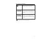
Notes, Cautions, and Warnings Note: Denotes helpful information intended to provide tips for better use of the product. Caution: Denotes a hazard. Failure to follow instructions could result in minor personal injury and/or property damage. Included text gives proper procedures. Warning: Denotes a hazard. Failure to follow instructions could result in SEVERE personal injury and/or property damage. Included text gives proper procedures.
This page intentionally left blank.
1.0 Introduction ETS-Lindgren’s Azimuth Positioner (AP) is designed to perform two-dimensional measurements (or manual three-dimensional measurements) of spherical antenna patterns. The AP includes a vertical support column that will accommodate EUTs up to 11.33 kg (25 lbs). The height of the vertical support column must be specified at the time the order is placed as each is built according to the customer’s specified height.
Standard Configuration • Model 2005 positioner motor base • LMF-3995 RS-232 RFI/EMI Filter • Custom vertical support • Coaxial rotary joint kit Optional Items • Phantom head (does not include solution) ETS-Lindgren Product Information Bulletin See the ETS-Lindgren Product Information Bulletin included with your shipment for the following: 8 • Warranty information • Safety, regulatory, and other product marking information • Steps to receive your shipment • Steps to return a component for
2.0 Maintenance Before performing any maintenance, follow the safety information in the ETS-Lindgren Product Information Bulletin included with your shipment. Disconnect the power before proceeding with recommended maintenance. Do not perform maintenance while the positioner is operating. Warranty may be void if the housing is opened. If you have any questions concerning maintenance, contact ETS-Lindgren WARRANTY Customer Service.
• • Inspect drive belt and pulleys periodically for excessive wear. Check cables for wear. Ensure they are clear of potential damage from moving parts. • Periodically inspect the Speed Reducer, located in the gearbox, for any signs of impending service. The following items may indicate need for service: • Oil leaking from seals—indicates that shaft and/or seals are worn and need replacing. Keep dirt and foreign particles off shafts in the area of the seals to minimize wear.
Replacement and Optional Parts Following are the part numbers for ordering replacement or optional parts for the Model 2005 Azimuth Positioner. Replacement Parts Part Description Part Number Serial Cable (set of two) 675282 (D89M to D89F, 15 ft.) Coaxial Rotary Joint Kit 890817 Tabletop Posts (set of three) 108689 Tabletop Absorber AF323280.20CL (must order all three) AF32380.
Service Procedures For the steps to return a system or system component to ETS-Lindgren for service, see the Product Information Bulletin included with your shipment. Filter Maintenance Recommendations Preventative maintenance is not required for power filters.
3.0 LMF 3995-RS232 RFI/EMI Filter Filter Specifications Current 4 x 0.006 amps Voltage 0-30 VAC/VDC Impedance 5000 ohms (L-L) Passband ± 1.
Marking and Documentation The filter contains an identification label that states manufacturer’s name, model of filter and serial number. The label also establishes the frequencies of operation, voltage, current rating and impedance (if applicable). The filter contains necessary labels indicating which terminals are grounded, danger of high voltage and the need for discharging of capacitors.
Safety Precautions • Ensure power is disconnected from the filter prior to beginning any work. • After the covers are removed and prior to beginning any work or prior to touching any electrical connector, ensure the filter is discharged by shorting all filter terminals to the filter case with a metallic object that has an insulated handle. Be careful to touch the terminal very softly and not damage the terminal. • Read and understand all warning labels affixed to the filter.
This page intentionally left blank.
4.0 Pre-Installation Tasks Before installing any components, follow the safety information in the ETS-Lindgren Product Information Bulletin included with your shipment. Ensure power is off and base is secured before proceeding with installation. Pre-planning is essential for successful installation. Discuss requirements with your sales representative and request dimensional drawings prior to construction of your site.
This page intentionally left blank.
5.0 Assembly and Installation Before install any components, follow the safety information in the ETS-Lindgren Product Information Bulletin included with your shipment. Positioner Installation Proper installation of the Azimuth Positioner (AP) unit directly affects performance of the positioning system as well as the accuracy of the test results. 1. Uncrate all parts. Check all parts for any shipping damage. Ensure a clear area is available to assemble the AP unit safely.
3. Position the AP so that the connections on the turntable are easily accessible and located closest to available feed through panels and power supply connections. Verify that the supplied serial cable, as well as any user supplied RF cable(s), is long enough to reach from the AP unit to the feed through panel that will include the RS232 filter before settling on an orientation. 4.
9. Finally, place the remaining two absorber pieces on the outer portion of the motor base 10. Install the vertical support column onto the motor drive mount by placing it over the pegs on top of the motor base. 11. Finally, floor absorber (provided by the customer) may be placed around the motor base to prevent RF interference from the positioner itself.
Electrical Installation Electrical connection should only be performed by a qualified electrician and subject to location electrical codes. The Model 2005 Azimuth Positioner (AP) is designed to operate using 110/220 VAC single phase 50 or 60 Hz power. The branch circuit supplying power to the motor base must be protected from excess current according to local electrical codes. ETS-Lindgren has provided integral circuit protection in the motor base assembly.
Filter Installation The filter is equipped with a 1 in. inside / 1.3 in. outside diameter (2.5cm inside/3.3cm outside) standard pipe penetration conduit kit. This includes pipe, conduit nut, brass nut, washer, circular EMI gasket and plastic cap. A 1.35 in. (3.429cm) hole must be made in the shield of the room in order to accommodate the conduit penetration of the filter. Drawings are included for reference during installation.
• Thread the conduit penetration and DB-9 connector through the hole on the shield, making sure that the circular gasket presses against the shield • Hold the conduit nut on the inside of the filter in order to have the washer and nut installed from the inside of the shielded room. Two people may be necessary to perform this step. • Screw the brass nut on the conduit penetration and tighten by hand. Using an adjustable wrench, apply an additional ¼ of a turn clockwise to the brass nut.
Filter Penetration Pipe Assembly Filter dimension outline Assembly and Installation | 25
This page intentionally left blank.
6.0 Operation Before operating any components, follow the safety information in the ETS-Lindgren Product Information Bulletin included with your shipment. See “Verifying Communication with Model 2005 Azimuth Positioner” at www.ets-lindgren.com, 2005 Positioner, Related Links for additional information.
Model 2005 Azimuth Positioner Command Set Command Format Set Speed (0-3) SX (x = 0,1,2,3) Example S1 Description Sets speed for AP: S0 = 0.25 rpm S1 = 0.5 rpm S2 = 1 rpm S3 = 2 rpm Query Speed S? Returns speed setting (0-3) Continuous CR In the continuous mode Rotation of operation the AP is allowed infinite movement. The AP travels from 0 – 359.
Command Set CC Limit Format LLxxx.x Example LL000.0 Description Sets CC limit in non- (x = 000.0–999.9) continuous mode. Query CC Limit LL? Returns CC limit Query Motion DIR? Reports motion Direction direction: CW, CC or N (no motion) Seek SKxxx.x SK180.0 (x=000.0—999.9) Seeks specified target in degrees A carriage return (0x0D) must be sent at the end of every command. An acknowledge byte (0x06) is returned after all non-query commands.
This page intentionally left blank.
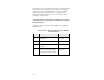
Appendix A: Warranty See the Product Information Bulletin included with your shipment for the complete ETS-Lindgren warranty for your Model 2005 Azimuth Positioner and LMF-3995 RS-232 RFI/EMI Filter. DURATION OF WARRANTIES FOR MODEL 2005 AZIMUTH POSITIONER AND LMF-3995 RS-232 RFI/EMI FILTER All product warranties, except the warranty of title, and all remedies for warranty failures are limited to the duration specified in the table.
This page intentionally left blank.