
Specifications

EATON Screw-In Cartridge Valves E-VLSC-MC001-E2 May 2015C-26.A
C
Where measurements are critical request certified drawings. We reserve the right to change specifications without notice.
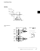
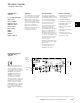
Ramp time: Turn clockwise
to increase ramp time.
Gain: Turn clockwise to
increase gain.
Deadband compensation:
Turn clockwise to increase
deadband compensation
current.
Dither: Turn clockwise to
increase the dither current.
Terminal 1: Power Supply
18 - 36V DC, positive.
Terminal 2: Power Supply 0V.
Terminal 3: Switch command
signal positive.
Terminal 4: Not connected
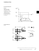
WARNING
Electromagnetic
Compatibility (EMC)
- Screened cables
should be used and particular
attention paid to the grounding
of the screens as shown in the
above diagram.
•�
123
4
Protective ground connection
24V
0V
>11 V
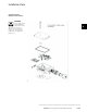
Installation Wiring
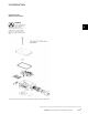
Installation Data
Adjustments
EATON DPPP Catalog October 20112
The gain of the valve is the ratio of the opening of the valve
(or flow rate from it) to the applied voltage input to the power
plug. The ramp rate is the rate at which the power plug allows
the valve to open (or close) when a step voltage input is ap-
plied to the power plug. In many applications this ramp would
be used to gradually accelerate or decelerate an actuator.
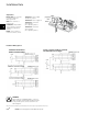
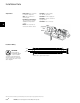
Installation precautions to eliminate leaks into the power
plug:
• Use only cables with circular cross-sections and diameter
between 5–10 mm (.2” - .4”)
• Ensure that sealing grommet is present and installed
correctly. It must be forced over the outer jacket of the
cable.
• Ensure that all the gaskets are present and properly
seated.
• Ensure that the plastic cover seats firmly and correctly on
the center body post.
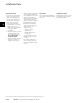
Connection diagram for CAN version (EHH-AMP-702-N-C-N-3-30)
This procedure describes the adjustments on the Power Plug
for setting the dead-band, gain and ramp rate on a non-feed-
back proportional valve. Proportional valves with over-lapped
spools have a range of spool travel where there is no flow
from the valve. This range of spool motion is called dead-
band. Adjusting the power plug allows the dead-band to be
electronically eliminated (dead-band Compensation) by mak-
ing the spool jump across the dead-band when a small input
signal is applied to the power plug.
Set-up Procedure
e – Cable connection option
1 – PG9 cable clamp
2 – M16 cable clamp
3 – M12 5 pin connector
Features and Benefits
• Integral amplifier provides essential functions for control
of proportional valves.
• Adjustable ramp time, gain, dead band compensation
through potentiometer or RS232/CAN communication (via
software).
• Ease of installation, with reduced cost.
• Fully short-circuit and reverse-polarity protected.
• Differential voltage command signal.
• Options with RS232 and CAN communication.
• Peak and Hold Functionality.
• PG9, M16 cable clamp and M12 connector options.
• Adjustable dither.
• EMC to latest European standards.
• Protection to IP67
• Available with CANOpen communications
Application
• Designed for the control of direct-operated, non-feed-
back, proportional valves where the cost of more com-
plex electronic controls can be avoided.
This product has been designed and tested to meet specific standards outlined in the European Electromagnetic Compatibility
Directive (EMC) 89/336/EEC, amended by 91/263/EEC, 92/31/EEC and 93/68/EEC, article 5. For instructions on installation
requirements to achieve effective protection levels, see this leaflet and the Installation Wiring Practices for Vickers Electronic
Products leaflet 2468. Wiring practices relevant to this Directive are indicated by Electromagnetic Compatibility (EMC).
.B