
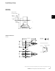
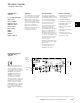
Specifications

EATON Screw-In Cartridge Valves E-VLSC-MC001-E2 May 2015C-22.A
C
Where measurements are critical request certified drawings. We reserve the right to change specifications without notice.
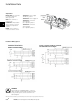
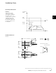
Installation Data
Start-Up Procedure
• With the plug correctly wired
but not mounted to the load
provide with a DC power
supply (See table).
• Apply the command signal
(ON) and check the Power
ON LED (RED) illuminates.
Reduce the signal to the
Command signal (OFF) level
and check the LED (RED)
goes out.
• If there is malfunction to the
LED replace the plug.
• Switch off the power sup-
ply and command signal
and connect the plug to the
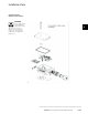
load. Ensure that the inter-
face seal is correctly fitted
and clamped between the
mounting faces (essential for
IP65 protection). Tighten the
retaining screw.
• Ensure that no damage
or injury will occur on the
machine when the valve is
operated.
• Switch on the power supply.
Apply the command signal.
(a) Observe Power On LED
(RED) is ON.
(b) Observe PWM LED
(Orange) is ON.
If LED is not operated then
there is short circuit in the
load. Replace the load/load
coil.
• Successful completion of
these steps means that the
plug and load are ready for
normal use.
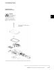
Spare Parts
The only spare part available is
the interface seal, part number
732100.
Ordering Procedure
Order plug by full model code,
and spare interface seals by
part number 732100.
.B