
Specifications

EATON Screw-In Cartridge Valves E-VLSC-MC001-E2 May 2015 C-17.A
C
Where measurements are critical request certified drawings. We reserve the right to change specifications without notice.
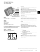
EHH-AMP-702-D/K-* Series
For use with valve types:
EPV**-12D-1*
EFV1-**-012DE*
ERV1/2**-12D-1*
EPRV1/3**-12D-1*
ESV1**-12D-1*
IRV**-012D-1*
PFR21*
PFR24*
PDR21A*
PPD22**-012D-1*
Note: This product has been
designed and tested to meet
specific standards outlined in
the European Electro-magnetic
Compatibility Directive (EMC)
89/336/EEC, amended by
91/26/EEC, 92/31/EEC and
93/68/EEC, article 5. For
instructions on installation
requirements to achieve
effective protection levels, see
this leaflet and the Installation
Wiring Practices for Vickers
Electronic Products leaflet
2468. Wiring practices relevant
to this Directive are indicated
by a warning symbol and
Electromagnetic Compatibility
(EMC).
Electronic Controls
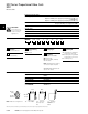
Proportional Valve
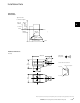
Control Power Plugs
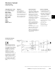
Electrical Block Diagram
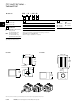
EHH-AMP-702-D/K-*
Application
Primary applications
are in the control of
non-feedback proportional
valves where the cost of
more sophisticated electronic
controls can be avoided.
Type J is typically used in
closed-loop applications.
General Description
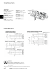
Three types of plugs,
conforming to ISO 4400/DIN
43650 interface, with integral
amplifiers and necessary
adjustment potentiometers,
are designed for use with
non-feed back hydraulic valves.
This plug/valve combination
offers very low cost solutions
to many hydraulic control
problems requiring
proportional control.
Type D is controlled with a
0-10V command signal, and
has adjustable gain, ramp,
deadband compensation
and dither.
For closed-loop and no ramp
applications adjust the ramp
port to minimum setting.
Type K is controlled with a
4-20 mA command signal, and
has an adjustable ramp time
of 50 ms to 5s.
Features and Benefits
• Integral amplifier provides
essential functions for
control of proportional valves
• Adjustable ramp time (types
D and K), gain, deadband
compensation and dither
• Ease of installation, with
reduced cost
• Fully short-circuit and
reverse-polarity protected
• Differential voltage command
signal (type D)
• Adjustable dither
• EMC to latest
European standards
• Protection to IP67
EATON DPPP Catalog October 2011 3
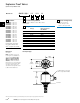
Connection diagram for CAN version (EHH-AMP-702-N-C-N-3-30)
Pin Number Description
1 CAN Shield
2 Supply Positive
3 Supply GND
4 CAN H
5 CAN L
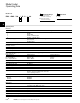
Electrical Block Diagram
Connection Diagram
Connection diagram for RS232 Versions (EHH-AMP-7XX-X-R-P-X-30)
Connector Pin Number Description
Supply 1 Supply Positive
Connector 2 Supply GND
3 Command + (For G type - Joystick I/P)
4 Command – (For G type - +5V reference)
Communication 1 NC
Connector 2 RXD
3 TXD
4 GND
Note:
When the selection switch position is changed, the input impedance for
the command input also changed. It is 249 Ohm for current command input
and 10K Ohm for voltage command input. The PTC (positive temperature
coefficient) in series with the command signal and the transzorb across the
input impedance of command signal will protect if the switch is at current
command and the voltage command is applied externally. For the correct
solenoid valve operation, it is necessary to check the command switch
position before applying the command input as per shown above. Switch
position is also identified by communication. When changing from Voltage
to current command (or vice versa) the switch has to be moved in the correct
position and the unit has to be configured via software (GUI) for the voltage
or current input.
.B