C Coils and Electronic Controls Solenoid valve and Proportional valve coils and electronic controls for proportional valves Where measurements are critical request certified drawings. We reserve the right to change specifications without notice. EATON Screw-In Cartridge Valves E-VLSC-MC001-E2 May 2015 C-1.
Coils and Electronic Controls Section Contents Typical Application Pressure bar (psi) Model Page Coils C ToughCoils™ Information.................................................................................................................................................. C-3 ToughCoils™ Model Code and Specifications.................................................................................................................. C-4 S Series ..........................................................
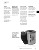
ToughCoils™ Information ToughCoils™ ToughCoils™ Features Eaton/IH ToughCoils™ have been designed to provide industry leading environmental protection and solenoid performance in a compact and rugged package. ToughCoils™ with integrated connectors are rated up to IP69K environmental protection. ToughCoils™ are available with a variety of popular integrated connection options and with wire leads.
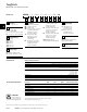
ToughCoils Model Code S,P,J and H Series Coils MCSC – * – *** – * – ** – * – ** – 10 Model Code 1 1 C 5 Function MCSC - Solenoid coil 2 Series S - Size 8 (210 Bar) P - Size 8 (350 Bar) J - Size 10, 12, 16, 20 (210 Bar) H - Size 10, 12, 16, 20 (350 Bar) 3 Voltage Rating 012 - 12 volt 024 - 24 volt 036 - 36 volt 048 - 48 volt 115 - 115 volt 230 - 230 volt 4 2 3 4 Connector G0 - ISO 4400 DIN 43650 Q0 - Spade Terminals W0 - Flying lead N0 - Deutsch Male, DT04-2P, Integrated (DC Only) Mating
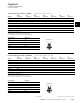
ToughCoils For 8 Size Solenoid Valves S & P Series Coils S Series ToughCoils part numbers - 300AA00____ (Complete Part number is 11 Digits) G0** Q0 Voltage Connector Connector W0 Connector N0 Connector Y0 Connector D0 Connector J0 Connector 12VDC 001A 009A 015A 021A 026A 031A 036A 24VDC 002A 010A 016A 022A 027A 032A 037A 36VDC 003A 011A 017A 023A 028A 033A 038A 24VAC 004A 012A 018A – – – – 115VAC 005A – – – – – – 230VAC 006A – –
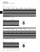
ToughCoils For 10, 12, 16 and 20 Size Solenoid Valves J & H Series Coils 300AA00____ (Complete Part number is 11 Digits) C G0** Q0 Voltage Connector Connector W0 Connector N0 Connector Y0 Connector 12VDC 081A 089A 095A 101A 106A 111A 116A 24VDC 082A 090A 096A 102A 107A 112A 117A 36VDC 083A 091A 097A 103A 113A 118A 24VAC 084A 092A 098A – – – – 108A – D0 Connector J0 Connector 115VAC 085A – – – 230VAC 086A – – – – – – –
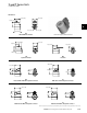
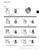
S and P Series Coils J & H Series Coils Dimensions 29,5 [1.16] 34,3 [1.35] 28,0 [1.10] C 31,8 [1.25] 12,9 [.51] 39,7 [1.56] G0 DIN 43650-A Connector 17,5 [0.69] 34,5 [1.36] Shown with integrated Deutsch Connector 29,5 [1.16] 26,2 [1.03] 26,2 [1.03] 28,0 [1.10] W0 Q0 Spade Connector Leadwire 35,6 [1.40] 37,1 [1.46] 31,2 [1.23] 23,4 [.92] 24,9 [.98] 34,8 [1.37] 27,9 [1.10] N0 Y0 Deutsch Male DTO4-2P integrated connector 37,6 [1.48] 35,1 [1.38] 29,7 [1.
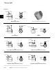
J Series Coils Dimensions 33,5 [1.32] (.685) C 29,5 [1.16] 31,5 [1.24] 46,5 [1.83] Ø 38,9 [1.53] 12,9 [.51] G0 DIN 43650-A Connector 34,3 [1.35] (.685) Shown with integrated MetriPack 150 Connector 29,5 [1.16] 26,2 [1.03] 29,7 [1.17] 31,5 [1.24] Q0 Spade Connector W0 Leadwire 35,3 [1.39] 36,8 1.45] 34,8 [1.37] 5,1 [.20] 28,4 [1.12] 38,4 [1.51] 31,5 [1.24] N0 Deutsch Male DTO4-2P integrated connector 35,1 [1.38] 33,3 [1.31] Y0 AMP Junior Timer integrated connector 37,6 [1.48] 27,7 [1.
H Series Coils Dimensions 33,5 [1.32] (.685) 29,5 [1.16] C 31,5 [1.24] 46,5 [1.83] Ø 38,9 [1.53] 17,6 [.69] G0 DIN 43650-A Connector 34,3 [1.35] (.685) Shown with integrated MetriPack 280 Connector 29,5 [1.16] 26,2 [1.03] 29,7 [1.17] 31,5 [1.24] Q0 Spade Connector W0 Leadwire 35,3 [1.39] 5,1 [.20] 36,8 1.45] 34,8 [1.37] 28,4 [1.12] 38,4 [1.51] N0 Deutsch Male DTO4-2P integrated connector Y0 AMP Junior Timer integrated connector 37,6 [1.48] 35,1 [1.38] 33,3 [1.31] 31,5 [1.
R & L Series Coils For SVx-12-3 and SVx-12-4 Solenoid Valves L Series Coils (“EN490” Coils) DC Coils Connector Voltage “G” DIN 43650 Connector “W” Leadwires Only 12V 02-309454 02-309452 24V 02-309455 02-309453 Full Power Coils: C Note: For more information on “L” series coils, please refer to Eaton Technical datasheet 5049/EN/0596/A (Solenoid Operated Directional Valve-DG4V-35, EN490 for Mobile Equipment).
C13 and C16 Series Coil Information Duty Rating FPO Electrical Connection Bobbin Encapsulation Copper Winding Iron Frame/Yoke Location of “O” ring seal between coil and tube Wattage C13 (for 13 mm tubes) C16 (for 16 mm tubes) The coil is rated for continuous operation at nominal voltage +/- 10% and an ambient range of -20 to +40.
C13 and C16 Series Solenoid Coil C13 – H – 24 / 22 Model Code 2 1 1 C 4 3 Coil Series 3 C13 - 13 mm tube 12 12 VDC 24 24 VDC 110 110 VRAC 220 220 VRAC* C16 - 16 mm tube 2 Connection HDIN43650 ISO Standard F - Flying Leads (12 and 24 VDC only) DM - Deutsch Moulded (12 and 24 VDC only) (Consult factory for other options) 4 Voltage Wattage C13 14 = 14 Watt 22 = 22 Watt 27 = 27 Watt C16 19 = 19 Watt 29 = 29 Watt *220 to 240 VAC All AC coils must be used with a rectifying connector
Explosion Proof Valves For hazardous environments Coil Options (SV*E Series) Specifications Hydraulic Performance Specifications for explosion proof valves are the same as the base valve. For details please refer to the base valve page reference.
Explosion Proof Valves (SV*E Series) Model Code Model Code 1 C SV*E-**(V)-* *** **** U 1 2 3 4 Base Valve SV1E-10-C SV1-10-C SV2E-10-C SV2-10-C SV3E-10-C SV3-10-C SV4E-10-C SV4-10-C SV1E-16-C SV1-16-C SV2E-20-C SV2-20-C SV4E-10-0 SV4-10-0 SV3E-10-0 SV3-10-0 SV5E-10-0 SV5-10-0 SV3E-16-0 SV3-16-0 SV3E-20-0 SV3-20-0 SV1E-10-3 SV1-10-3 SV1E-10-4 SV1-10-4 SV2E-10-4 SV2-10-4 SV3E-10-4 SV3-10-4 SV4E-10-4 SV4-10-4 For performance specifications refer to base valve data sheet.
EPV Series Proportional Valve Coils EPV Coils Control and specifications Rheostat 12 VDC operation 10-12 , 20-25 watts 24 VDC operation 25-30 , 20-25 watts EHH-AMP-702, EPAD-SA-1A6-10 (Require 24 VDC power supply to power plug and 12 VDC coil) EEA-PAM-523 (Requires 24 VDC power supply and either 12VDC or 24 VDC coil) OEM Controls, Inc, Shelton, CT P-Q Controls, Inc, Bristol, CT Power plug options Amplifier card Joystick suppliers Std. Voltages Amperes* Lead Color Power Rating 12 DC 24 DC 1.32 .
EFV Series Proportional Valve Coils EFV M Series Coils Control and Specifications Power plug options EHH-AMP-702 (Requires 24 VDC power supply to power plug and 12 VDC coil) EHH-AMP-712 (Requires 12 VDC power supply to power plug and 12 VDC coil) EHH-PAM-600 (Requires 24 VDC power supply and 12VDC) DIN Rail Module C CAUTION Coils may be hot to touch if used in continuous duty applications.
Electronic Controls Proportional Valve Control Power Plugs EHH-AMP-702-D/K-* Series Application General Description Features and Benefits For use with valve types: Primary applications are in the control of non-feedback proportional valves where the cost of more sophisticated electronic controls can be avoided. Three types of plugs, conforming to ISO 4400/DIN 43650 interface, with integral amplifiers and necessary adjustment potentiometers, are designed for use with non-feed back hydraulic valves.
Model Code/ Operating Data Model Code 1 EHH - AMP - 702 - * - R - P - * - 30 1 2 Adjustment Range D-P roportional plug: 0-10 VDC with ramp K-P roportional plug: 4-20 mA with ramp 2 Cable Gland 1 - PG9 2 - M16 C Operating Data Electrical Types D Connections 1 24V DC 2 Supply GND 3 Positive command signal 4 Negative command signal Power (input) supply 18-36V DC including ± 10% maximum ripple (peak-to-peak) 24V DC nominal Absolute maximum voltage 40V Max.
Installation Data Input/Output Characteristics Type K and D Type J Type K and D signal Command Command Type K signal Type D 20KmA Type 10V Type D 8V 20 mA 12 mA 10V 6V 8V 4V 6V 2V 12 mA 4 mA 4V 2V 4 mA Output current Output current Ramp setting Ramp setting USX Gain setting USX Deadband Gain setting compensation Deadband compensation J Type Command signal Command voltage U s signal voltage U s10V 8V 10V 6V 8V 4V 6V 2V 4V Time 2V Time Output current Output current Time Time C Time Time USX Gain sett
1 – PG9 cable clamp 2 – M16 cable clamp 3 – M12 5 pin connector Installation Data • Protection to IP67 • Available with CANOpen communications Features and Benefits • Integral amplifier provides essential functions for control of proportional valves. • Adjustable ramp time, gain, dead band compensation through potentiometer or RS232/CAN communication (via software). • Ease of installation, with reduced cost.
Installation Data Assembly Showing Wiring Connection Points WARNING Ensure cable clamp nut is adequately tightened to secure cable. Do not connect, or disconnect, the plug while power is on. Do not mount, or dismount, the plug while power is on. •� Assemblies C *All seals must be fitted correctly at plug installation to provide protection to IP67 (IEC 529). Warning: • Ensure cable clamp nut is adequately tightened to secure the cable.
Installation Data Start-Up Procedure C • With the plug correctly wired but not mounted to the load provide with a DC power supply (See table). •S witch on the power supply. Apply the command signal. • Apply the command signal (ON) and check the Power ON LED (RED) illuminates. Reduce the signal to the Command signal (OFF) level and check the LED (RED) goes out. (b) Observe PWM LED (Orange) is ON. • I f there is malfunction to the LED replace the plug.
Electronic Controls “Soft Switch” Power Plugs EHH-AMP-702-C-* 10 Series For use with valve types: EPV**-12D-1* EFV1-**-012DE* ERV1/2**-12D-1* EPRV1/3**-12D-1* ESV1**-12D-1* IRV**-012D-1* PFR21* Application General Description Features and Benefits Focus applications for this plug are in the control of hydraulic solenoid operated directional and pressure control valves where control of valve response time can significantly reduce shocks in the hydraulic system.
Model Code/ Operating Data Model Code EHH - AMP - 702 - C - * C Operating Data Electrical Connections 1 24V DC 2 OV (power and signal) 3 Positive command signal 4 Negative command signal Power (input) supply 18 - 36V DC including ± 10% maximum ripple ripple (peak-to-peak) 24V DC nominal Absolute maximum voltage 40V Max.
Installation Data Input/Output Characteristics Type K and D Functions Type J Command signal Switch-on/off: after Type K Type D switching on with a 20 mA 10V 11V signal the amplifier 8V will remain in the “on” 6V 12 mA 4V condition with a command 2V signal above 6V. The 4 mA command signal must be reduced to below 5V Output to achieve switch-off of current the amplifier.
Installation Data e – Cable connection option 1 – PG9 cable clamp 2 – M16 cable clamp 3 – M12 5 pin connector Adjustments Features and Benefits • • C Ramp time: Turn clockwise to increase ramp time. Gain:functions Turn clockwise to Integral amplifier provides essential for control increase gain. of proportional valves. Deadband compensation: Adjustable ramp time, gain, dead band compensation Turn clockwise to increase through potentiometer or RS232/CAN communication deadband compensation (via software).
Installation Data Assemblies Assembly Showing Wiring Connection Points WARNING Ensure cable clamp nut is adequately tightened to secure cable. Do not connect, or disconnect, the plug while power is on. Do not mount, or dismount, the plug while power is on. •� C *All seals must be fitted correctly at plug installation to provide protection to IP67 (IEC 529). Warning: • Ensure cable clamp nut is adequately tightened to secure the cable. • Do not connect, or disconnect, the plug while power is on.
Installation Data Start-Up Procedure •C orrectly wire the plug and, before mounting it on the valve solenoid, apply 24V DC (18 to 36V limits) to the “power input” terminals. C •C heck for correct plug function by illumination/ non-illumination of the LED: a. Apply less than 2 to 3 volts to the input terminal: LED should not be illuminated. b. I ncrease voltage: the LED should illuminate when the voltage reaches 11V. Do not exceed 30V command signal. c.