
Specifications
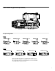
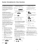
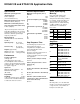
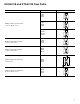
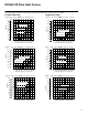
Table Of Contents
8
KDG4V-3S and KTG4V-3S Application Data
Maximum current @ 50C (122 F)
ambient
G 3.2A
H 1.6A
Power Consumption @ 20C (68F)
G 18 Watts
H 18 Watts
GP 30 Watts
HA 30 Watts
Coil Resistance @ 20C (68 F)
G 1.8 Ohms
H 7.3 Ohms
GP 4.9 Ohms
HA 19.6 Ohms
Coil Inductance @ 1000 Hz
G 7.5 mH
H 29 mH
GP 16 mH
HA 67 mH
The following response times were
measured from the point of
energization/de-energization to the
point of first indication of inlet
pressure change.
Response up to full system pressure is
dependent on the system’s
compressed volume and can vary with
each application.
0–100% (center to full spool travel)
100 msec
100–0% (full spool travel to center –
fast drop out)
15 msec
10–90% (10% full flow to 90% full flow)
100 msec
90–10% (90% full flow to 10% full flow)
25 msec
100–100% (100% full flow travel in
one direction to 100 % full flow travel
in the reverse direction)
80 msec
Step Response Time
Drain
On 2-way valves, “T” is the drain and
must be connected to the tank through
a surge-free line, so there will be no
back pressure at this port.
Solenoid Specifications
Specifications
Maximum operating pressure
(A, B and P ports)
350 bar (5000 psi)
(See “Flow Gain Curves”)
Maximum tank line pressure (T port)
K*G4V-3S:100 bar (1450 psi)
Maximum recommended pressure
drop (four–way models at max. flow)
210 bar (3000psi)*
*At pressure drops above 10 bar (145
psid) dither amplitudes in the electronic
controller may need to be set at or near
minimum to eliminate potential high
frequency circuit noise.
Mounting pattern
ISO–4401–AB–03–4–A, NFPA D03,
CETOP 3
Operating temp 20 to 82C. . .
(–4 to 180F)
Fluid viscosity 16 – 54 cSt. . .
(75–250 SUS)
Weights (approximate)
KDG4V–3S–*–60 2,3 kg (5.06 lbs.). .
KTG4V–3S–*–60 1,75 kg (3.85 lbs.). .
Performance
Frequency Response
18Hz @ –3db
(10Hz @ 45 degree phase lag)
For an amplitude of 25% max stroke
(center to offset) about the 50% position
and DP (P–A–B–T) = 10 bar (145 psid).
See graph on page 14.
Hysteresis
With pulse width modulation: 4%
With direct DC voltage
(GP & HA): 8%
Repeatability: 1%
Deadband : 15–35%
of full solenoid input. Vickers electronic
controllers have a deadband eliminator
to reduce this value to near zero.
Spool, Spool/Spring,
Metering
Refer to the table below for the
available spools, spool/spring
arrangements and metering conditions.
For example, if a KD valve with a “33”
spool is required, the spool/spring
arrangement is “C” and the metering
condition available is “A”. Refer to
“Model Code” for a definition of
these codes.
Model Spool
Spool/Spring
Arrangement
Metering
Condition
C
C
KD
KT
N
A
EEA–PAM–523–A–32
EEA–PAM–523–B–32
EEA–PAM–523–C–32
EEA–PAM–523–D–32
EEA–PAM–523–E–32
EEA–PAM–523–F–3
2
Amplifiers
Plug Amplifier
EHH–AMP–702–C–20
EHH–AMP–702–D–20
EHH–AMP–702–E–20
EHH–AMP–702–F–20
Amplifier
Coil Voltage
Identification
Letter
GP
HA
H
EEA–PAM–520–A–14
(for use with EN427
models)
G EHH–AMP–712–D/G–20
Refer to drawing I-521575 for information.
EM–VT–12–10
EM–VP–12–10
EM–VT–24–10
EM–VP–24–10
H
H
B or F
B
2
33
2
33
N or S
A