
Specifications
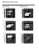
Table Of Contents

6
System Calculations for Valve Selection
The “rated flow” values for this range of
proportional valves are determined with a
looped flow path pressure drop (e.g.
P→A→B→T) of 10 bar (145 psi) when the
valve is fully open. As explained on page
4, however, “rated flow” is an arbitrary
term dependent upon
external factors.
It is important to properly size a
proportional valve to achieve good
resolution. A common mistake in specifying
proportional valves is selecting too high a
rated flow. The result may be poor control
of the actuator, particularly with respect to
velocity and resolution. The ideal valve
size is usually one that provides just
enough maximum flow to achieve the
required actuator velocity.
The following steps can be used to
determine the proper size for a proportional
valve. This procedure applies to a
conventional four-way valve controlling an
equal area piston driving a load in an
application in which velocity is the critical
parameter. For differential area cylinders,
base the calculations on the maximum
cylinder flow rate.
Constants
A = Actuator piston area, cm
2
(in
2
)
F
M
= Maximum force required, N (lbf)
F
D
= Force required to accelerate and
maintain velocity, N (lbf)
P
S
= Supply pressure less other
system pressure drops, bar (psi)
P
L
= Maximum pressure required to
drive or accelerate actuator under
dynamic conditions, bar (psi)
P
V
= Allowable valve pressure drop,
bar (psi)
V = Desired actuator velocity,
m/s (in/s)
Q = Flow required to drive actuator at
desired velocity, L/min (USgpm)
1. Determine required actuator area:
A(cm
2
) +
F
M
(N)
10 P
S
(bar)
ƪ
A(in
2
) +
F
M
(lbf)
P
S
(psi)
ƫ
2. Determine flow required to drive
actuator at desired velocity:
Q(Lńmin) + 6 A(cm
2
) V(mńs)
ƪ
Q(USgpm) +
A(in
2
) V(inńs)
3.85
ƫ
3. Determine maximum load pressure
drop under dynamic conditions:
P
L
(bar) +
F
D
(N)
10 A(cm
2
)
ƪ
P
L
(psi) +
F
D
(lbf)
A(in
2
)
ƫ
4. Determine valve pressure drop:
P
V
(bar) + P
S
(bar) * P
L
(bar)
ƪ
P
V
(psi) + P
S
(psi) * P
L
(psi)
ƫ
5. Refer to Flow Gain Curves starting on
page 10 and determine most suitable
valve spool based on flow (Q) and
pressure drop (P
V
).
6. Refer to Power Capacity Envelopes on
page 13 and verify that flow (Q)
determined in step 2 at the valve
pressure drop (P
V
) determined in step
4 falls within (to the left of) the power
curve for the spool selected in step 5.
Example
A hydraulic system consisting of a
pressure compensated pump, proportional
valve, and equal area cylinder must
develop a maximum force of 6400 N (1440
lbf) and move a 200 N (45 lbf) load at a
velocity of 0,25 m/s (9.84 in/s).The force
required to maintain this velocity is 1000 N
(225 lb), and the pump’s compensator is
set at 60 bar (870 psi).
1. Determine required actuator area:
A +
F
M
10 P
S
+
6400
10 60
+ 10,7 cm
2
ƪ
A +
F
M
P
S
+
1440
870
+ 1.66 in
2*
ƫ
* 2 inch bore, 1.375 inch rod cylinder
has actuator area = 1.66 in
2
2. Determine flow required to drive
actuator at desired velocity:
Q + 6 A V
+ 6 10,7 0,25 + 16,1 Lńmin
+
1.66 9.84
3.85
+ 4.24 USgpm
ƫ
ƪ
Q +
A V
3.85
3. Determine maximum load pressure
drop under dynamic conditions:
P
L
+
F
D
10 A
ƪ
P
L
+
F
D
A
+
225
1.66
+ 136 psi
ƫ
+
1000
10 10, 7
+ 9, 4 bar
4. Determine valve pressure drop:
ƪ
P
V
+ P
S
* P
L
P
V
+ P
S
* P
L
+ 60 * 9, 4 + 50, 6 bar
+ 800 * 136 + 734 psi
]
5. Refer to Flow Gain Curves and
determine most suitable valve spool
based on flow (Q) and pressure drop
(P
V
):
Calculated flow (Q) is 16,1 L/min (4.24
USgpm), and valve pressure drop (P
V
) is
50,6 bar (734 psi). Reference to the
KDG4V-3S “Flow Gain” graphs (see page
10) shows that the 15N spool (meter-in and
meter-out) will do the job. A
KDG4V–3S–2C15N would be selected.